Planar antenna member and plasma processing apparatus including the same

a technology of plasma processing and antenna member, which is applied in the direction of plasma technique, solid-state diffusion coating, coating, etc., can solve the problems of insufficient examination of the surface structure (slot pattern) of the planar antenna suited for electromagnetic waves of, e.g., about 1 ghz, which is lower than the conventional microwave frequency, and the inability to generate surface wave plasma. stably, the effect of introducing electromagnetic waves

Inactive Publication Date: 2011-05-19
TOKYO ELECTRON LTD
View PDF3 Cites 2 Cited by
  • Summary
  • Abstract
  • Description
  • Claims
  • Application Information

AI Technical Summary

Benefits of technology

[0007]The present invention has been made in view of the above circumstances. The first object of the present invention is to provide a planar antenna capable of efficiently introducing electromagnetic waves having a frequency lower than the conventional microwave frequency, into a chamber. The second object of the present invention is to provide a plasma processing apparatus that uses electromagnetic waves having a frequency lower than the conventional microwave frequency, the plasma processing apparatus having a high controllability over a plasma and being capable of stably generating a surface wave plasma in the chamber, even when a large substrate is processed.

Problems solved by technology

For example, when a plasma process is carried out under a condition where a pressure in the chamber is 133.3 Pa or more, the plasma density may not sufficiently increase.
Thus, the surface structure (slot pattern) of a planar antenna suited for electromagnetic waves of, e.g., about 1 GHz, which is lower than the conventional microwave frequency, has not been sufficiently examined.
First of all, a plasma processing apparatus using electromagnetic waves of lower frequency such as 1 GHz or less is not equipped with a planar antenna itself, because the generation of a surface wave plasma is difficult.
However, even when a planar antenna, which was manufactured based on theoretically calculated length of a slot and layout of the slots, is used to generate a plasma, there is no guarantee that a surface wave plasma is always stably generated.
In an actual operation of such a large planar antenna, even when the length of a slot and the layout of the slots are set as theoretically optimum values, it is difficult to stably maintain a surface wave plasma.

Method used


Image

  • Planar antenna member and plasma processing apparatus including the same
  • Planar antenna member and plasma processing apparatus including the same
  • Planar antenna member and plasma processing apparatus including the same

Examples


first embodiment

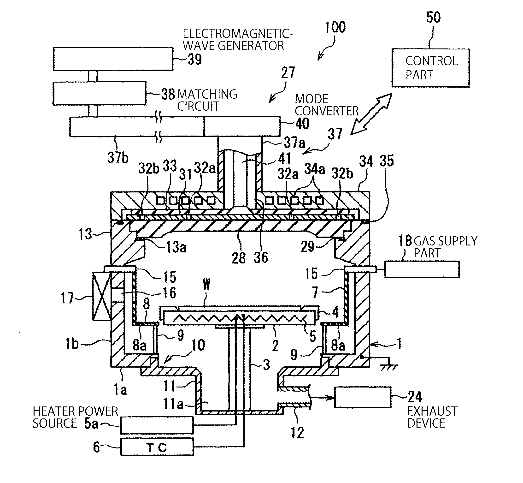
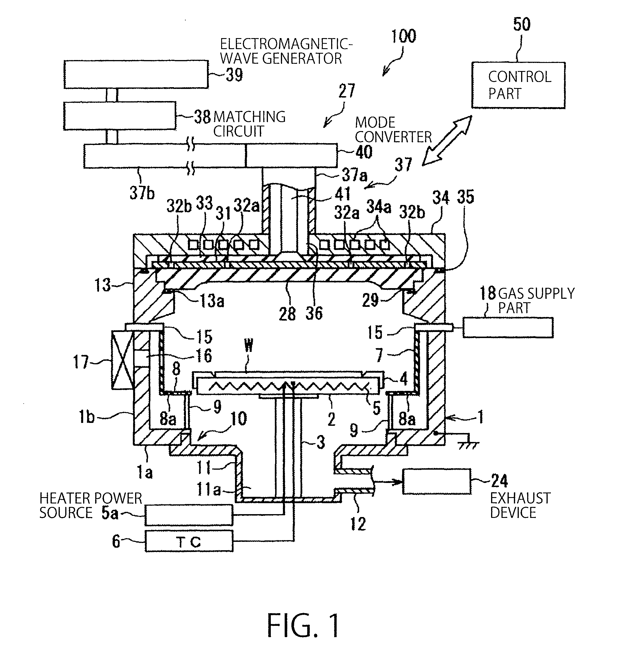
[0029]Embodiments of the present invention will be described in detail below with reference to the drawings. FIG. 1 is a sectional view schematically showing a plasma processing apparatus 100 in a first embodiment according to the present invention. FIG. 2 is a plan view of a main part of a planar antenna plate (planar antenna member) in the first embodiment according to the present invention, which is used in the plasma processing apparatus 100 of FIG. 1. FIG. 3 is an enlarged view of a slot as a through-hole in the planar antenna plate. FIG. 4 is a block diagram showing an example of a schematic structure of a control system in the plasma processing apparatus 100 of FIG. 1.

[0030]The plasma processing apparatus 100 is constructed as a plasma processing apparatus configured to generate a plasma of a high density and a low electron temperature, by introducing electromagnetic waves into a processing vessel, by means of a planar antenna plate having a plurality of slot-like through-hol...

second embodiment

[0086]Next, with reference to FIGS. 6 and 7, there will be described a planar antenna plate 61 in a second embodiment according to the present invention. FIG. 6 is a plan view showing a main part of the planar antenna plate 61 in the second embodiment, and FIG. 7 is an enlarged plan view showing a slot in the planar antenna plate 61. Similarly to the planar antenna plate 31 in the first embodiment, the planar antenna plate 61 in this embodiment is used in the plasma processing apparatus 100.

[0087]The planar antenna plate 61 has a base member 61a of a circular plate shape, and a lot of pairs of slots 62 (62a and 62b) formed in the base member 61a with a predetermined pattern. The planar antenna plate 61 has the same structure as that of the planar antenna plate 31 in the first embodiment, excluding that a width W2 of each slot 62 is larger and that the number of the slots 62 is smaller. Thus, in the following description, the differences from the first embodiment are principally desc...

third embodiment

[0095]Next, there will be described a planar antenna plate 71 in a third embodiment according to the present invention with reference to FIG. 8. FIG. 8 is a plan view showing a main part of the planar antenna plate 71 in the third embodiment. Similarly to the planar antenna plate 31 in the first embodiment, the planar antenna plate 71 in this embodiment is used in the plasma processing apparatus 100. The planar antenna plate 71 has the same structure as that of the planar antenna plate 61 in the second embodiment, excluding that the number of the slots arranged on the outer circumferential side is larger. Thus, in the following description, the differences from the second embodiment are principally described. The identical components are represented by the same reference numerals, and detailed description thereof is omitted.

[0096]The planar antenna plate 71 includes a base member 71 of a circular plate shape, and a lot of slots 72 (72a, 72b1, 72b2) formed in the base member 71a with...


PUM


Abstract

The present invention is a planar antenna member configured to introduce electromagnetic waves generated by an electromagnetic-wave generating source into a processing vessel of a plasma processing apparatus, the planar antenna member comprising: a base member of a circular plate shape, made of a conductive material; and a plurality of through-holes formed in the base member of a circular plate shape, the through-holes being configured to radiate the electromagnetic waves; wherein: the through-holes include a plurality of first through-holes which are arranged on a circumference of a circle whose center corresponds to a center of the planar antenna member, and a plurality of second through-holes which are arranged concentrically with the circle outside the first through-holes; a ratio L1/r is within a range between 0.35 and 0.5, in which L1 is a distance from the center of the planar antenna member to a center of one of the first through-holes, and r is a radius of the planar antenna member; and a ratio L2/r is within a range between 0.7 and 0.85, in which L2 is a distance from the center of the planar antenna member to a center of one of the second through-holes, and r is the radius of the planar antenna member.

Description

FIELD OF THE INVENTION[0001]The present invention relates to a planar antenna member used for introducing electromagnetic waves of a predetermined frequency into a processing vessel configured to plasma-process an object to be processed, and a plasma processing apparatus including the planar antenna member.BACKGROUND ART[0002]As a plasma processing apparatus configured to perform a plasma process such as an oxidizing process and a nitriding process to an object to be processed such as a semiconductor wafer, there is known a plasma processing apparatus of a type which generates a plasma by introducing microwaves of, e.g., 2.45 GHz frequency into a processing vessel, by using a planar antenna having a plurality of slots (for example, JP11-260594A and JP2001-223171A). Such a microwave plasma processing apparatus can form a surface wave plasma in a chamber, by generating a plasma having a high plasma density.[0003]In the plasma processing apparatus of the above type, when a pressure in ...

Claims


Application Information

Patent Timeline
Patent Type & Authority Applications(United States)
IPC IPC(8): C23C16/50H01Q13/10C23C8/10
CPCH01J37/32192H05H1/46H01J37/3222
Inventor UEDA, ATSUSHIADACHI, HIKARUTIAN, CAIZHONGFUKUDA, YOSHINORIHONGO, TOSHIAKIYOSHIOKA, MASAO
Owner TOKYO ELECTRON LTD
Why Eureka
Try Eureka