Height comparator

a comparator and height technology, applied in the direction of automatic grinding control, sport apparatus, skating parts, etc., can solve the problems of affecting the productivity of operators, affecting the efficiency of operators, and affecting the accuracy of operations

Inactive Publication Date: 2006-10-05
GUSPRO
View PDF13 Cites 16 Cited by
  • Summary
  • Abstract
  • Description
  • Claims
  • Application Information

AI Technical Summary

Benefits of technology

[0013] As another preference, a stop collar is included which slides over the support and can be secured thereto for setting a lower limit for the position of the measuring head.

Problems solved by technology

Such an operation can be awkward and inaccurate due to the size of the skate sharpening machine and the angle at which the operator would observe the alignment of the blade with respect to the grinding wheel.
The downtime between successive sharpenings to center each skate blade, can hinder the productivity of the operator.
Performing such a technique in the vicinity of the grinding wheel also poses the risk of the grinding wheel inadvertently powering on without warning, creating a hazard for the operator.

Method used


Image

  • Height comparator
  • Height comparator
  • Height comparator

Examples


Embodiment Construction

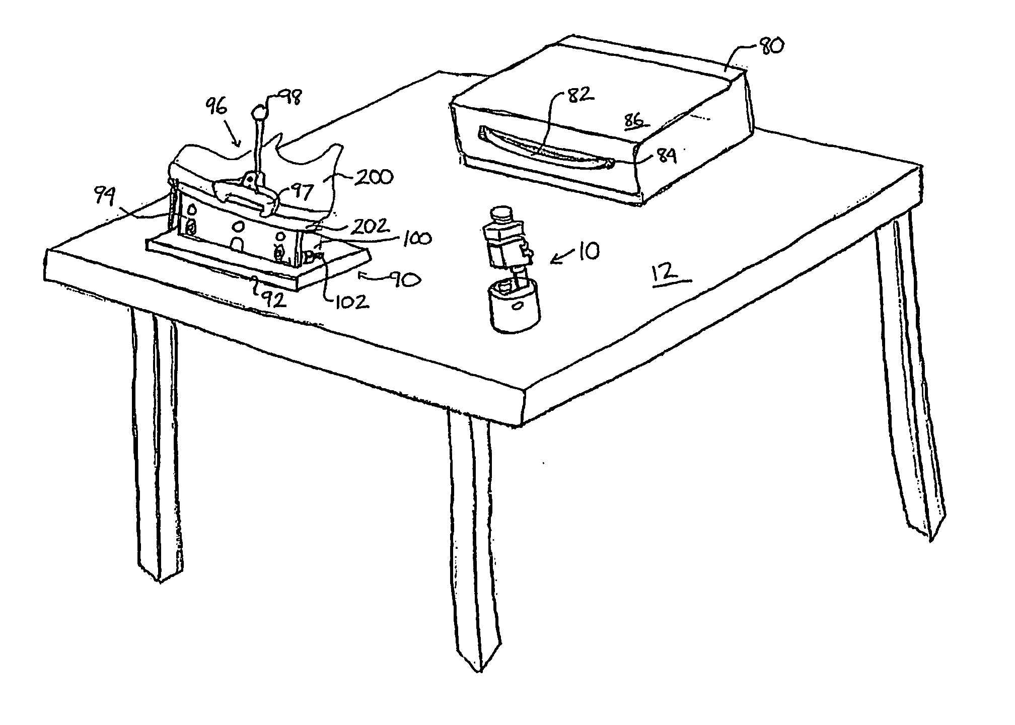
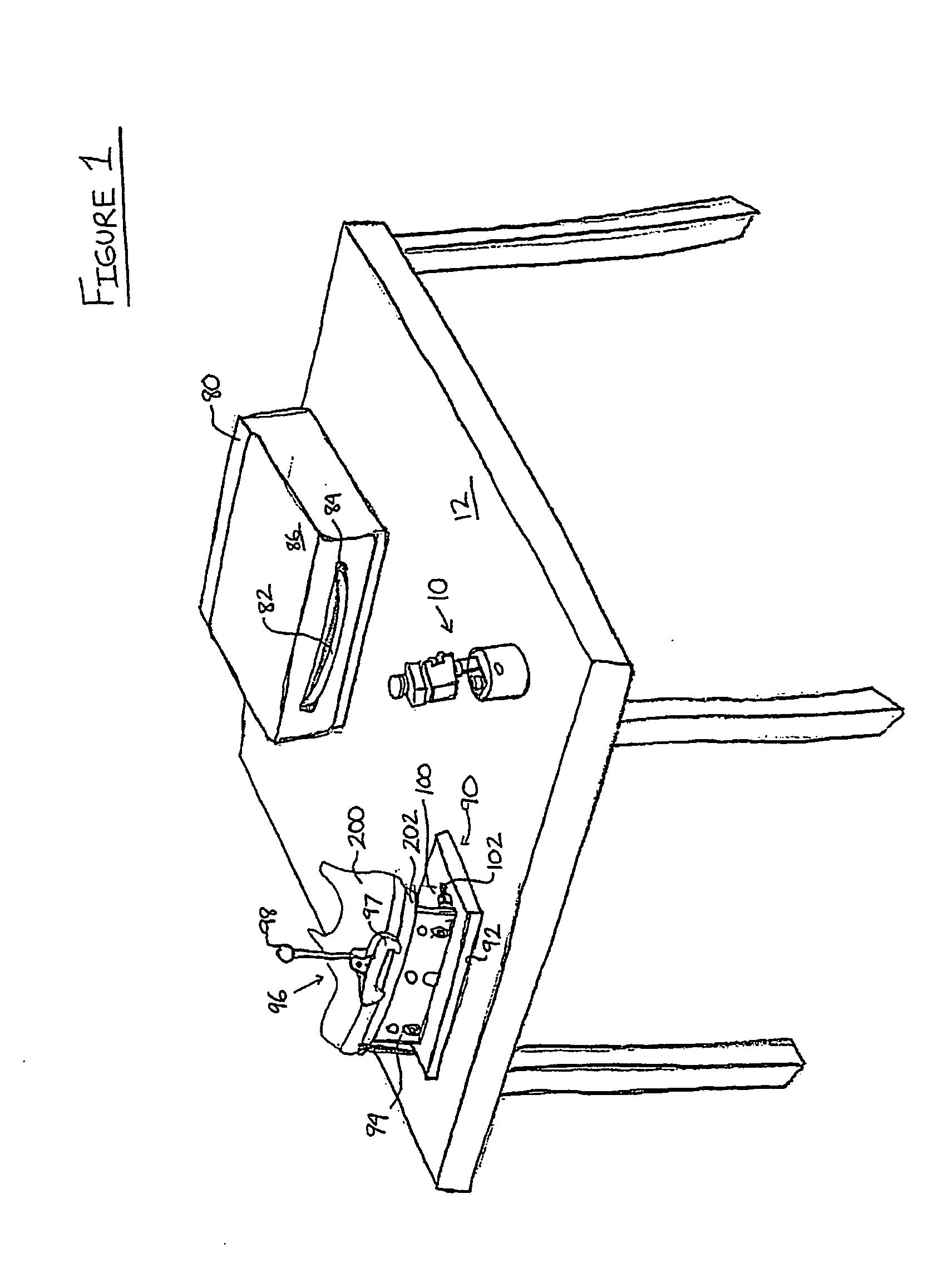
[0022] Referring therefore to FIG. 1, a typical skate sharpening environment is shown. A table has a working surface 12 that supports a skate sharpening machine 80. The working surface 12 is preferably made of a material that is attracted to a magnet. The machine 80 is mounted on the surface 12, and a portion of a grinding wheel 82 protrudes through a slot 84 formed in a shield 86. The surface 12 also supports a clamping-type skate holder 90. The holder 90 has a base 92 that rests on the surface 12. The base 92 supports a levelling plate 94 with a pair of levelling mechanisms 100 (one of them is not shown) having adjustment handles 102. A skate 200, having a blade 202, is clamped between the plate 94 and a jaw 97. The jaw 97 is part of a clamping mechanism 96, and is operated by pivoting a handle 98, which is also part of the clamping mechanism 96. A device for measuring the height of an object to be used in setting the height of another object is also supported on the surface 12 an...


PUM


Abstract

A device is provided for measuring the centre of a grinding wheel for use in setting the height of a skate blade. The device has a base, a support extending from the base, a slider block slidable along the neck between the base and a head block secured to an upper end of the neck, a dial indicator supported by the head block for measuring the position of the slider block along the neck, a lower roller, and an upper roller. The lower roller and upper roller are rotatably attached to the slider block and radially aligned with each other such that a portion of each roller protrudes from the slider block, wherein a clockwise tangential force imparted on the upper roller causes the slider block to slide along the neck, and the dial indicator to record the movement of the slider block, which enables the height of an object to be set on the dial indicator with respect to a rest position of the slider block.

Description

[0001] This application claims priority from U.S. Provisional Patent Application No. 60 / 667,689 filed Apr. 4, 2005.FIELD OF THE INVENTION [0002] The present invention relates to devices for measuring, comparing, and setting the height of an object and has particular utility in centring the hollow of a skate blade with respect to the grinding wheel of a skate sharpener. DESCRIPTION OF THE PRIOR ART [0003] The blade of an ice skate comprises a concave lower surface, providing a pair of edges at terminal ends of the concave surface. This concave surface is generally referred to as the “hollow” of the blade. To maintain the hollow, and thus the pair of edges, the skate is periodically sharpened using a skate sharpening machine. [0004] A typical skate sharpening machine is generally comprised of a table-top or working surface, and a motor driven grinding wheel mounted on the surface. In order to restore a blade's hollow, the grinding wheel is oriented substantially parallel to the workin...

Claims


Application Information

Patent Timeline
Patent Type & Authority Applications(United States)
IPC IPC(8): B24B49/00
CPCB24B49/00B24B3/003
Inventor MOON, ROBERT
Owner GUSPRO
Why Eureka
Try Eureka