
Systems and methods for coordinating the coverage and capacity of a wireless base station

a wireless base station and wireless network technology, applied in the field of wireless communication, can solve the problems of mobile devices most likely experiencing interference, power level reduction, and base station location, and achieve the effect of improving overall network coverage and capacity

Inactive Publication Date: 2006-10-05
ADAPTIX
View PDF7 Cites 35 Cited by
  • Summary
  • Abstract
  • Description
  • Claims
  • Application Information

AI Technical Summary

Benefits of technology

The present invention is a method for optimizing the performance of a wireless network by monitoring the traffic from other base stations and mobile devices within its coverage area. Based on these monitored conditions, the new base station determines the transmitting parameter configuration to achieve a desired optimization between capacity and coverage area. The new base station can also automatically adjust its antenna beams in elevation, pointing angle, and beam width. The invention allows for a central control to monitor the entire network and make corrective actions to improve overall network coverage and capacity. The invention can also minimize interference and optimize network performance.

Problems solved by technology

One problem experienced in wireless communication systems is locating base stations.
If on the other hand there are two mobile devices each on the edge of coverage with two base stations and if propagation were uniform those mobile devices would most likely experience interference.
If the transceiver continues to cause interference, or not properly cover the designated area network adjustments might have to be made, or the power level reduced further.

Method used


Image

  • Systems and methods for coordinating the coverage and capacity of a wireless base station
  • Systems and methods for coordinating the coverage and capacity of a wireless base station
  • Systems and methods for coordinating the coverage and capacity of a wireless base station

Examples


Embodiment Construction

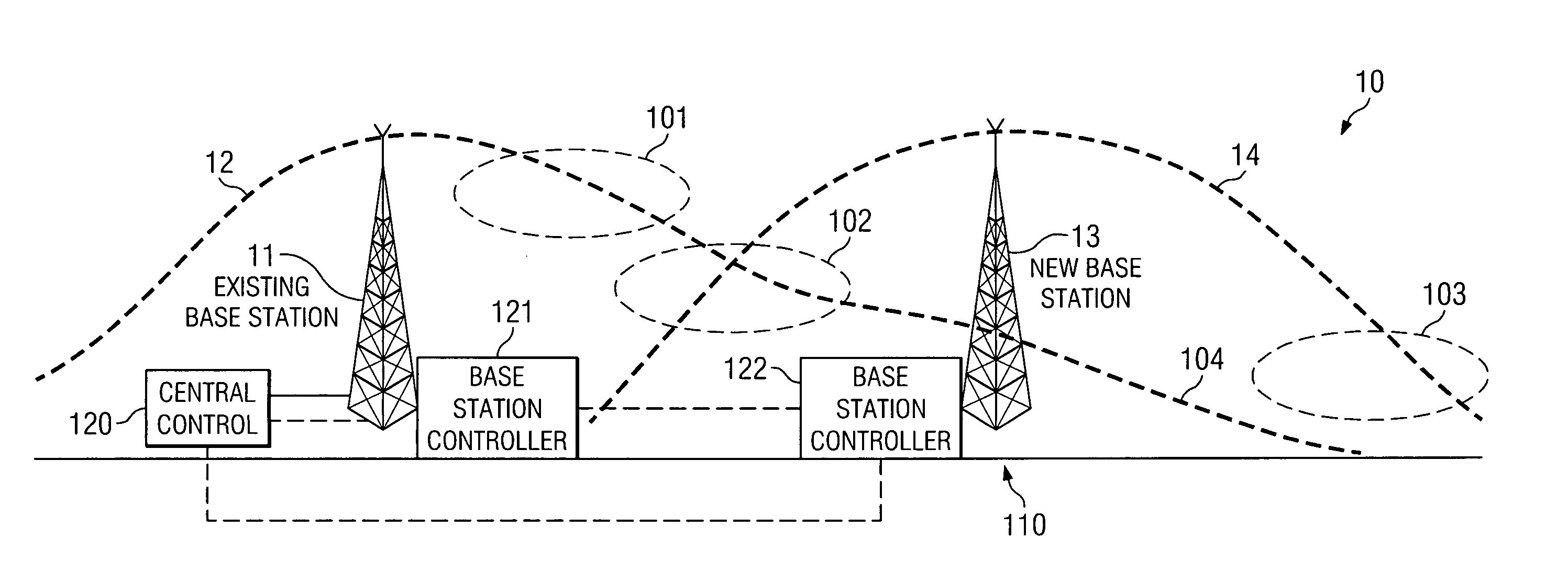
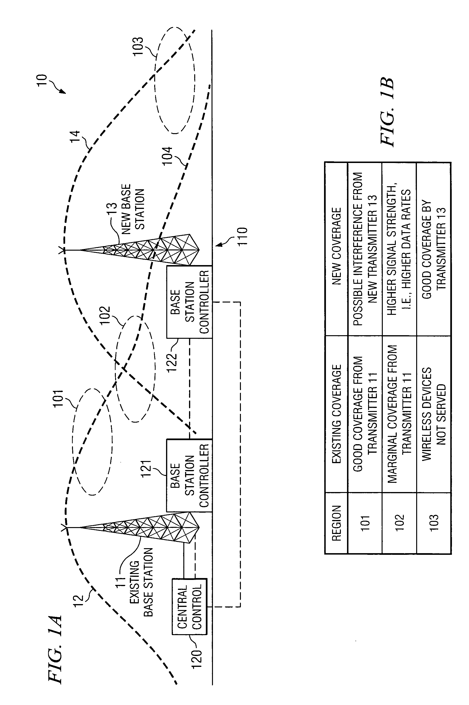
[0017]FIG. 1A shows wireless network 10 initially having one base station 11 with coverage area defined by dotted line 12. Transmission and other control to / from base station 11 is controlled by base station controller 121 in conjunction with central control (NOC) 120 which could be co-located with a base station, if desired. Contained within base station controller 121 is a database and at least one software program which controls transmission to / from the base station as is now well known. As will be seen, while transmission from base station 11 can, in theory, reaches out to point 104, transmissions to and from that location would most probably be unsatisfactory because of low energy. Since mobile devices, such as cell phones, PDAs, computers, two-way pagers and the like, do not transmit with as much energy as does a base station, most wireless devices would not be able to transmit as far as does the base station and thus the actual coverage area would be even less than shown by d...


PUM


Abstract

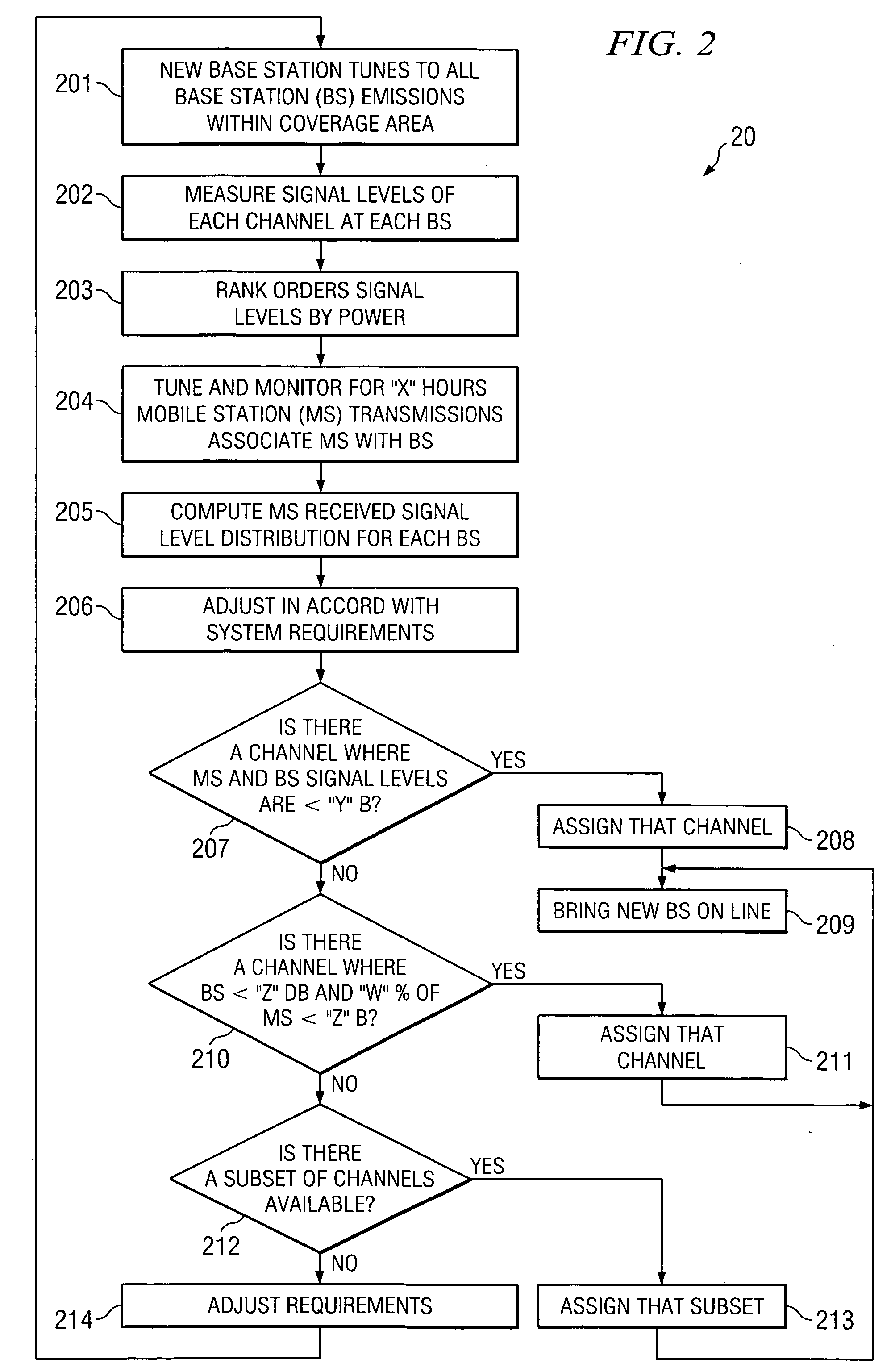
A communications base station is installed at a selected new location and the base station, prior to going “on line” monitors the wireless traffic from other base stations within interference range of the new base station's coverage area. The new base station also monitors the wireless traffic between mobile devices within its coverage area and these other base stations. Based upon these monitored conditions, as well as other known conditions, the new base station then determines the transmitting parameter configuration it should imply in order to achieve a desired optimization between capacity and coverage area. After the new base station is on line, a central control can monitor the entire network to determine if any additional changes are necessary and if so the new transceiver, or any other transceiver, can be instructed to monitor itself with respect to interference and to take corrective action to improve overall network coverage and capacity.

Description

TECHNICAL FIELD [0001] This Invention relates to wireless communication and more particularly to systems and methods for increasing base station coverage and capacity in a wireless network, and even more particularly to such methods and systems for placement of wireless transceivers within a communication network. BACKGROUND OF THE INVENTION [0002] One problem experienced in wireless communication systems is locating base stations. Once a base station (transmitter / receiver) is positioned in a coverage area it is important to be able to set its respective parameters in order to provided the desired coverage or capacity. [0003] In this context, coverage is the geographical area covered by the signals to or from the base station while capacity relates to the amount of data that can pass through the base station to or from mobile devices. Base stations can be optimized for either coverage area or capacity (throughput). Typically, such optimization has been accomplished by using a sophis...

Claims


Application Information

Patent Timeline
Patent Type & Authority Applications(United States)
IPC IPC(8): H04B17/00H04W16/06
CPCH04W16/10H04W16/28H04W88/10H04J11/0083H04W24/02H04W24/08
Inventor REUDINK, DOUGLAS O.
Owner ADAPTIX
Learn More