In vivo imaging device and method of manufacture thereof

Inactive Publication Date: 2006-10-05
GIVEN IMAGING LTD
View PDF38 Cites 128 Cited by
  • Summary
  • Abstract
  • Description
  • Claims
  • Application Information

AI Technical Summary

Benefits of technology

[0008] According to some embodiments of the present invention, the support, for example the circuit board may be manufactured or pre-provided to include one or more three-dimensional (3D) electrical packages for vertically packaging the components of the in-vivo device and so as to possibly reduce the amount of space taken up by the components. According to some embodiments of the present invention, 3D chip scale packaging solutions may help to meet size and performance requirements of the in-vivo imaging device by

Problems solved by technology

Several factors have so far limited the extent to which the size, weight and power consumption of an imaging device can be reduced.
Anot

Method used


Image

  • In vivo imaging device and method of manufacture thereof
  • In vivo imaging device and method of manufacture thereof
  • In vivo imaging device and method of manufacture thereof

Examples


Example

[0017] It will be appreciated that for simplicity and clarity of illustration, elements shown in the figures have not necessarily been drawn to scale. For example, the dimensions of some of the elements may be exaggerated relative to other elements for clarity. Further, where considered appropriate, reference numerals may be repeated among the figures to indicate corresponding or analogous elements.

DETAILED DESCRIPTION OF THE INVENTION

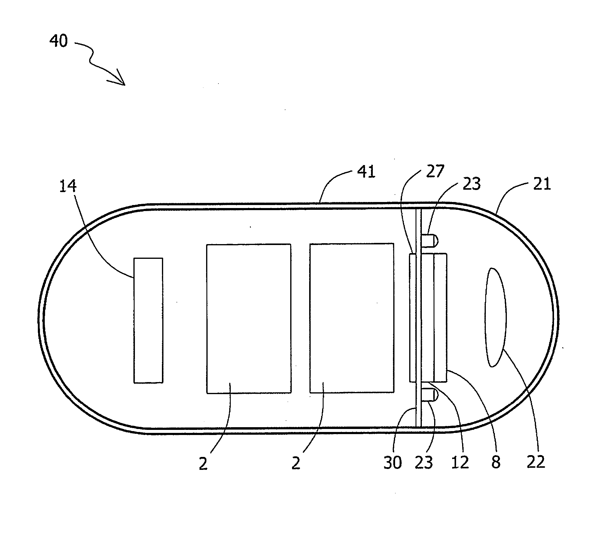
[0018] The following description is presented to enable one of ordinary skill in the art to make and use the invention as provided in the context of a particular application and its requirements. Various modifications to the described embodiments will be apparent to those with skill in the art, and the general principles defined herein may be applied to other embodiments. Therefore, the present invention is not intended to be limited to the particular embodiments shown and described, but is to be accorded the widest scope consistent with the principl...


PUM


Abstract

An in vivo imaging device including one or more components for example an imager, a transmitter and a circuit board having rigid sections and flexible sections According to some embodiments, the in vivo imaging device components may be electrically joined and/or stacked together using three-dimensional (3D) chip scale packaging solutions.

Description

FIELD OF THE INVENTION [0001] The present invention relates to an in vivo imaging device and system, such as, for example, for imaging the digestive tract or other body lumens. BACKGROUND OF THE INVENTION [0002] Known devices may be helpful in providing in-vivo imaging Autonomous in-vivo imaging devices, such as swallowable or ingestible capsules or other devices may move through a body lumen, imaging as they move along, Some of these devices use a wireless connection to transmit image data. [0003] In some in vivo devices, such as ingestible imaging capsules, the components within the capsule, such as an imager(s), may be arranged on a support and / or on a board or on several boards, for example on a printed circuit board (PCB). In some cases the boards are aligned along an axis of the capsule and are electrically connected by a plurality of wires. [0004] Several factors have so far limited the extent to which the size, weight and power consumption of an imaging device can be reduced...

Claims


Application Information

Patent Timeline
IPC IPC(8): A61B1/05
CPCA61B1/051A61B1/041
Inventor KHAIT, SEMIONGILAD, ZVIKA
Owner GIVEN IMAGING LTD
Why Eureka
Try Eureka