
System and method for laser lipolysis

Active Publication Date: 2006-10-05
EL EN SPA
View PDF29 Cites 76 Cited by
  • Summary
  • Abstract
  • Description
  • Claims
  • Application Information

AI Technical Summary

Benefits of technology

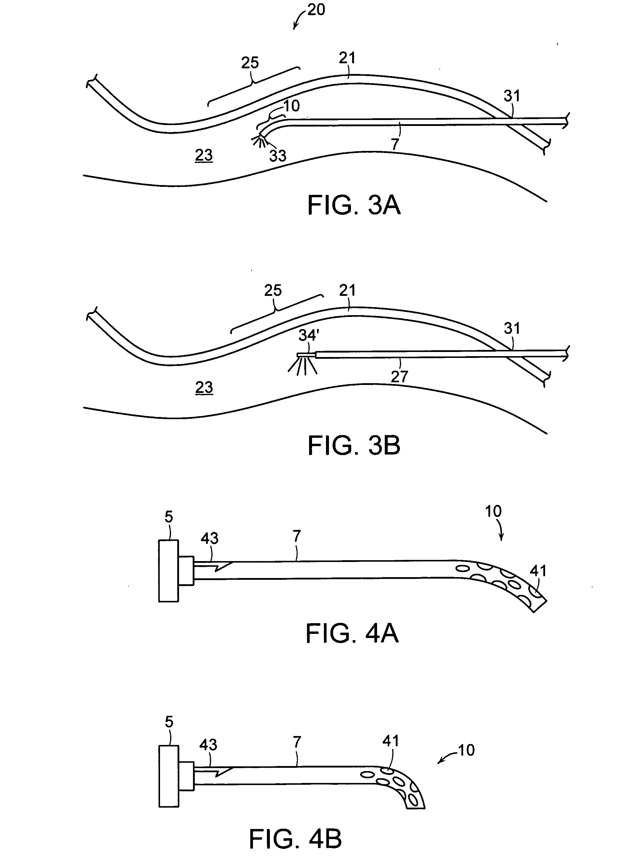
[0004] A problem with existing systems and methods for laser lipolysis is that the laser energy emitted from the tip of the cannula can often cause undesirable damage to the skin layers above the adipose layer. This problem is particularly acute when treating body areas having a curved, contoured shape, where slight movements of the cannula tip can cause the laser energy from the tip to penetrate into the overlying dermal layers and possibly perforate the skin. In one aspect, the present invention is a device for the removal of subcutaneous adipose layers that comprises a laser source; an optical fiber for conveying a laser beam emitted by the laser source; and a hollow cannula for guiding the fiber to the subcutaneous treatment area. The cannula has a curved or bent portion at its distal end, where the curved portion can be shaped to roughly conform to the contour of the patient's body structure. In this way, laser energy from the fiber, applied to the adipose layers, is generally directed away from the lower dermis of the patient, minimizing the risk of non-reversible damage to the dermis, including skin necrosis.
[0005] In one embodiment, the laser source is an Nd:YAG laser which emits a pulsed beam having a wavelength between approximately 0.75 and 2.05 μm, preferably between about 0.8 and 1.1 μm, and an energy between about 30 and 300 mjoules per pulse. The cannula is generally between 8 and 10 inches in length, and can have an external diameter of between about 1 and 2 mm. A second “aiming” laser, which emits visible light that is coupled into the optical fiber, can be employed to assist the operator in locating the tip of the cannula underneath the patient's skin.
[0006] In another aspect, a device for the removal of subcutaneous adipose layers comprises a first laser source; an optical fiber for conveying a laser beam emitted by the first laser source; a hollow cannula for guiding the fiber; and means for preventing the laser beam emitted by the first laser source from causing non-reversible damage to the dermis of the patient. In one embodiment, the means for preventing the laser beam from causing non-reversible damage comprises a curved portion at the distal end of the cannula to direct the laser beam away from the lower dermis. In another embodiment, a side-firing fiber emits the laser beam in the opposite direction of the dermis to minimize damage to the patient's dermis.

Problems solved by technology

A problem with existing systems and methods for laser lipolysis is that the laser energy emitted from the tip of the cannula can often cause undesirable damage to the skin layers above the adipose layer.
This problem is particularly acute when treating body areas having a curved, contoured shape, where slight movements of the cannula tip can cause the laser energy from the tip to penetrate into the overlying dermal layers and possibly perforate the skin.

Method used


Image

  • System and method for laser lipolysis
  • System and method for laser lipolysis
  • System and method for laser lipolysis

Examples


Embodiment Construction

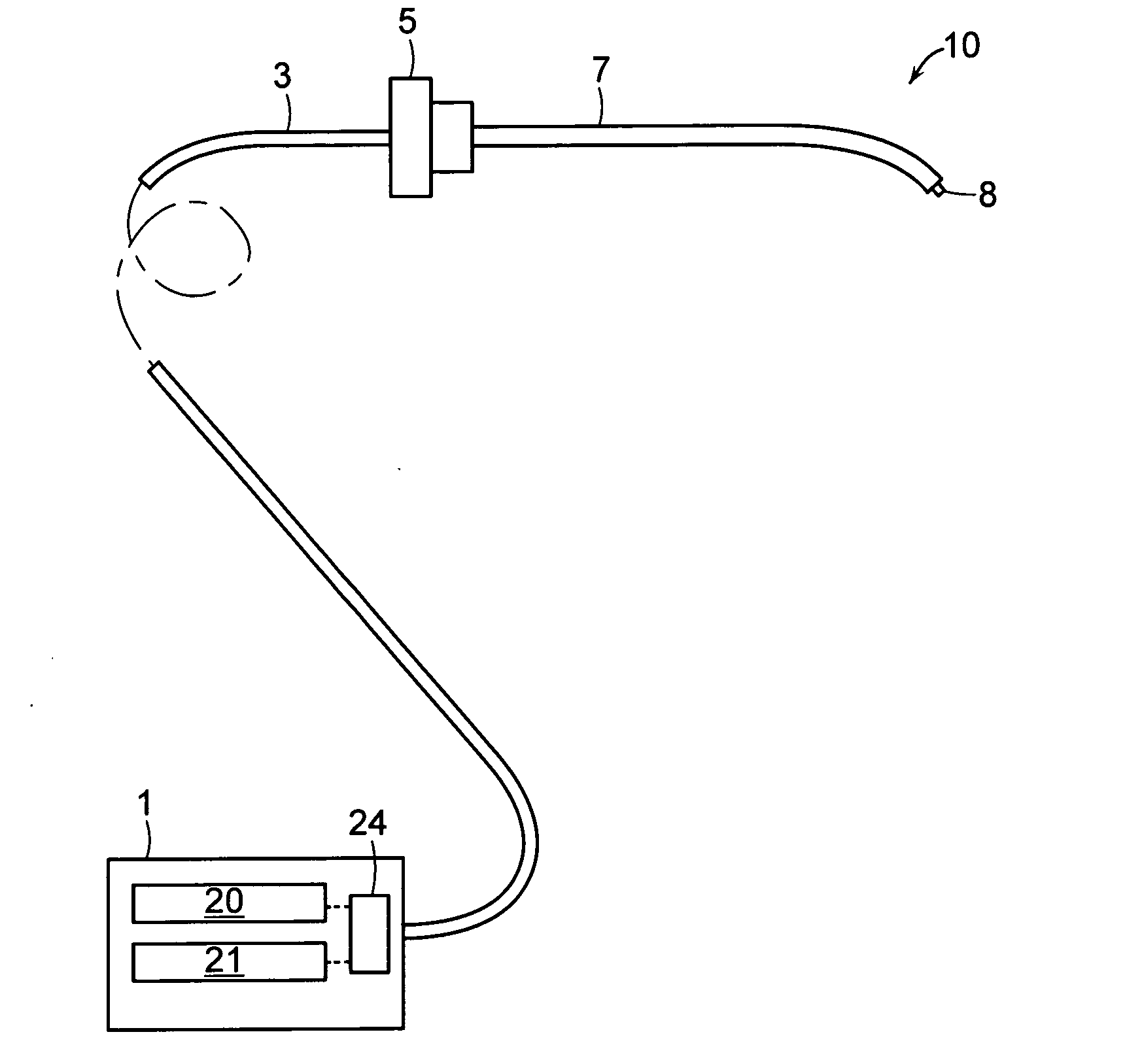
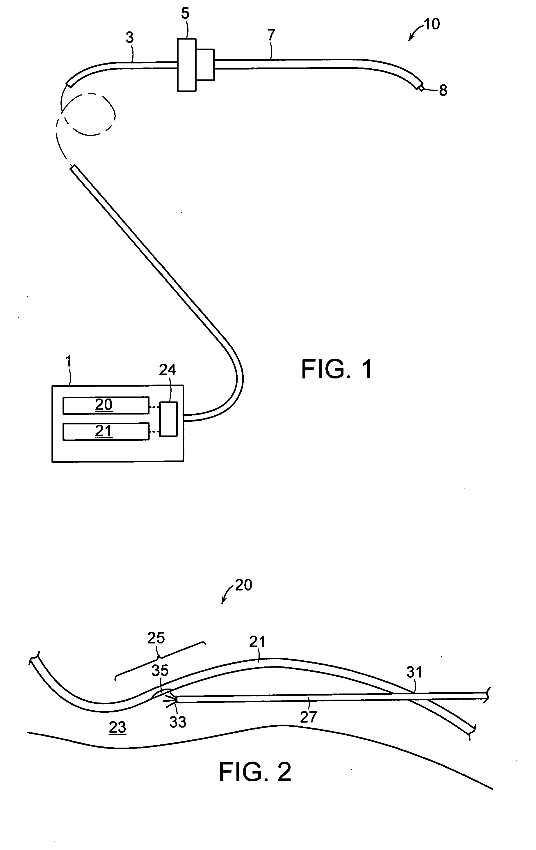
[0022] A description of preferred embodiments of the invention follows. With reference initially to FIG. 1, the device comprises a laser source 1 coupled to an optical fiber 3. The fiber 3 connects to a hollow cannula 7, and extends through the interior of the cannula 7, terminating at or near the cannula tip. Preferably, the proximal end of the fiber 3 protrudes out from the tip of the cannula 7 by approximately 1-2 mm. The fiber 3 can be connected to the cannula 7 using any conventional means, such as a Touhy-Borst connector 5, which holds the fiber tight within the cannula. In operation, laser energy from the source 1 is coupled into the fiber 3, and is conveyed along the length of the fiber to the cannula tip. The laser energy can thus be directed from the end of the fiber to a treatment site by controlling the location and orientation of the cannula tip.

[0023] The cannula 7 is a thin, needle-like structure, that is preferably made from stainless-steel. Generally, the cannula h...


PUM


Abstract

A device and related method for the removal of subcutaneous adipose layers comprises a laser source; an optical fiber for conveying a laser beam emitted by the laser source; and a hollow cannula for guiding the fiber to the subcutaneous treatment area. The cannula has a curved portion at its distal end, where the curved portion can be shaped to roughly conform to the contour of the patient's body structure. In this way, laser energy from the fiber, applied to the adipose layers, is generally directed away from the lower dermis of the patient, minimizing the risk of non-reversible damage to the dermis, including skin necrosis. In another embodiment, the optical fiber is a side-firing fiber that directs the laser energy away from the dermis. In other embodiments, a radiation detector, such as a thermal or optical sensor, monitors the temperature at the surface of the skin above the treatment area to warn the operator of harmful temperatures in the lower dermis. In another embodiment, a temperature sensitive material is applied to the surface of the skin above the treatment area to warn of harmful dermal temperatures. In another embodiment, a cooling mechanism cools the surface of the skin above the treatment area to prevent damage to the dermis.

Description

BACKGROUND OF THE INVENTION [0001] The reduction of subcutaneous adipose layers constitutes one of the most important areas of aesthetic treatments. A number of techniques currently exist for this purpose. One common technique, known as liposuction, consists of introduction into the adipose layers of probes roughly 5 mm in diameter through holes made in the skin of the patient undergoing treatment, for suction and removal of fat. This technique has a number of disadvantages, such as the creation of a lack of homogeneity in the form of depressions in the zone of insertion of the probe which are visible from the outside, as well as excessive bleeding of the patient undergoing treatment. Furthermore, both the cells of fat and the stroma are sucked out non-selectively. [0002] Another technique utilizes subcutaneous ultrasonic probes to rupture the membrane of the adipose cells, thus causing the escape of liquid which then has to be sucked out subsequently. In this case, suction of the s...

Claims


Application Information

Patent Timeline
IPC IPC(8): A61B18/18
CPCA61B18/22A61B2017/00057A61B2017/00084A61B2562/0276A61B2018/2288A61B2019/5437A61B2018/00005A61B2090/3937A61B2018/00464
Inventor CHO, GEORGE E.S.MASOTTI, LEONARDO
Owner EL EN SPA
Learn More