
System management architecture for multi-node computer system

a computer system and system management technology, applied in the direction of multiple digital computer combinations, etc., can solve the problems of significant delay and/or performance, smm processes and control and management thereof, multiprocessing (smp), etc., to reduce run-time internode traffic, improve access, and reduce the effect of interode traffi

Inactive Publication Date: 2006-10-05
LENOVO GLOBAL TECH INT LTD
View PDF21 Cites 19 Cited by
  • Summary
  • Abstract
  • Description
  • Claims
  • Application Information

AI Technical Summary

Benefits of technology

"The patent describes a system where each processor in a multi-node system can execute its own tasks using its own resources. This reduces the traffic between processors and allows for faster processing. The system also creates a map that identifies the specific resources of each processor, which helps improve performance. Overall, this system improves the efficiency and speed of processing in a multi-node system."

Problems solved by technology

SMM offers great flexibility for computer designers; however, it can also cause unintended problems if the execution time of this management code takes too much time away from the operating system.
This problem arises in symmetric multiprocessing (SMP) machines and can become particularly severe in large multi-chassis or multi-node computers (the terms “node” and “chassis” are used interchangeably herein).
Particularly in the case where the multiple nodes are interconnected to comprise large SMP machines, such as eight-way or 16-way SMP machines, the SMM processes and control and management thereof present significant delay and / or performance issues.
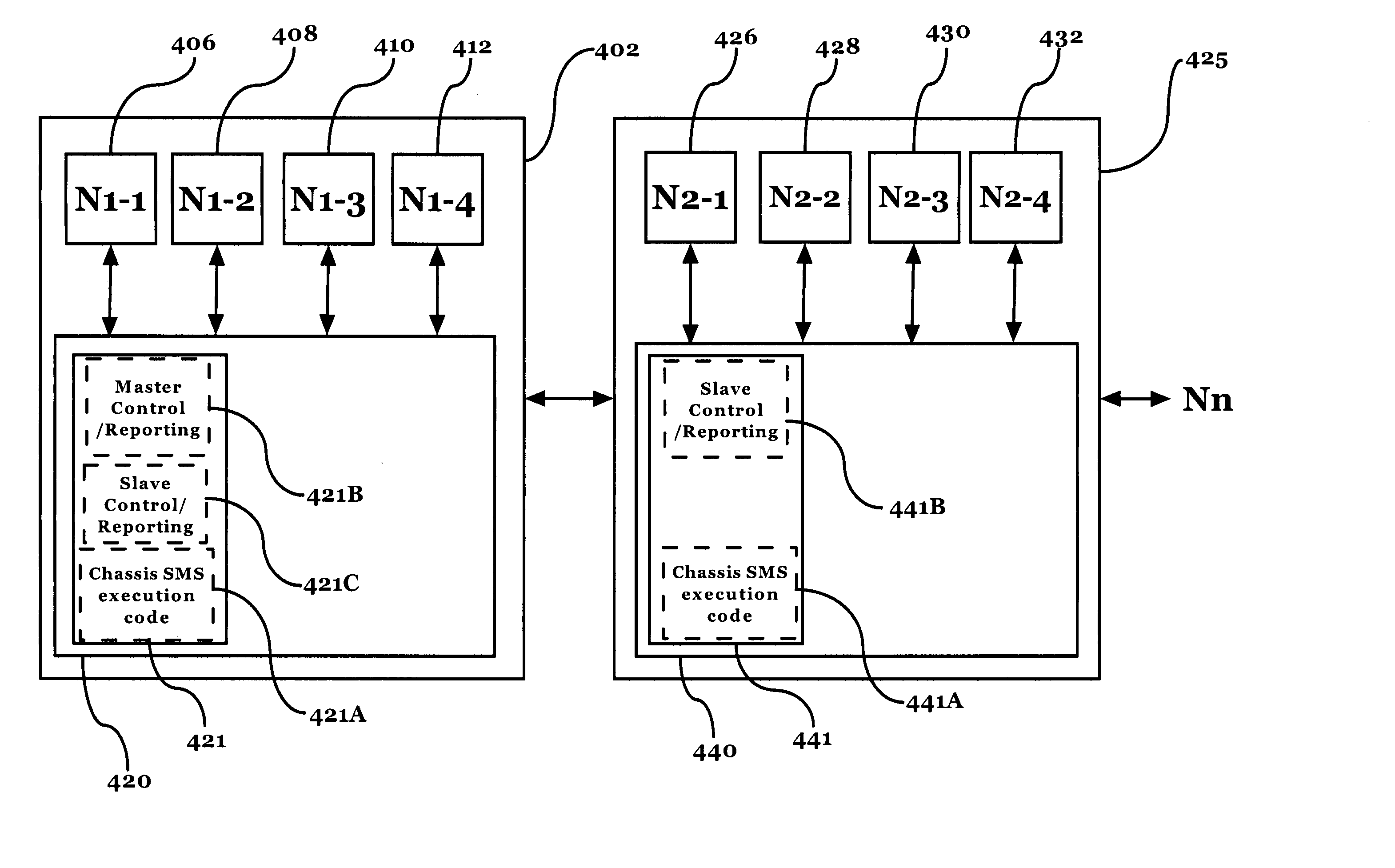
If Scheme 2 SMM processing is utilized, while it is true that all of the memory and I / O subsystems will be checked more quickly than in Scheme 1, it does not take advantage of the node architecture, since every CPU's task will be stored in and execute from the same base SMM resource space, hence creating inefficiencies in interconnection traffic, control and reporting, and root node SMM memory space utilization.

Method used


Image

  • System management architecture for multi-node computer system
  • System management architecture for multi-node computer system
  • System management architecture for multi-node computer system

Examples


Embodiment Construction

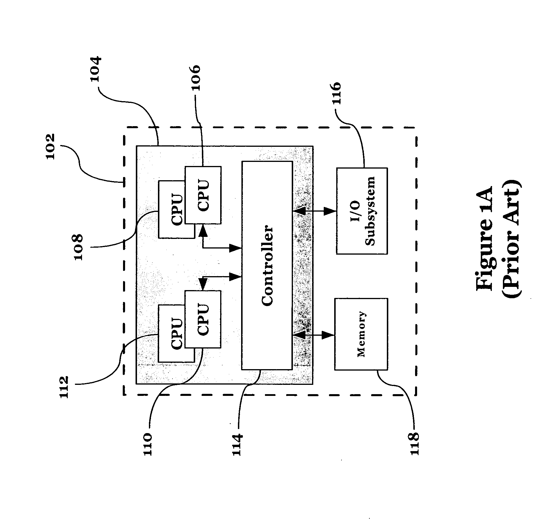
[0021]FIG. 1A illustrates a single node SMP system 102. The node 102 illustrated in FIG. 1A is a standard single node (sometimes also referred to as a single chassis) four-way configuration. The architecture illustrated in FIG. 1A is one example of an industry standard SMP system.

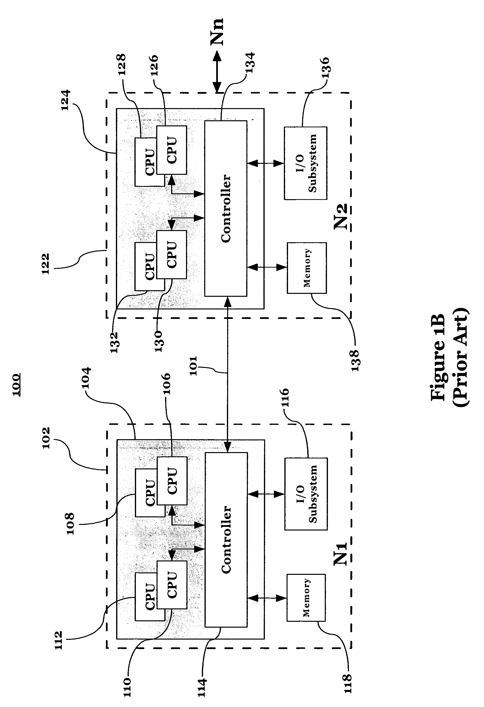
[0022] In node 102 of FIG. 1A, CPUs 106, 108, 110, and 112, as well as controller 114, reside on CPU card 104. Controller 114 controls the various operations between the CPUs and an I / O subsystem 116 and memory element 118. As noted above, the node 102 shown in FIG. 1A is a four-way configuration, since it has four CPUs within the node. Each CPU has equal access to all system resources (memory and I / O subsystem). This well known architecture has essentially four times the processing power of a single CPU configuration. FIG. 1B shows a multi-node configuration in which two four-way systems are interconnected with a high speed interface 101 (e.g., via scalability ports), allowing scalability. Scalability por...


PUM


Abstract

In a multi-node SMP system, at least one processor per node is enabled to execute the SMM task for the hardware resources that are local to that node. Additionally, each node is allocated its own local SMM code copy in its own SMM memory segment, to allow for improved access and a further reduction in internode traffic. In a preferred embodiment, only a signle processor per node is enabled to execute the SMM tasks, and specific SMM memory locations within the SMM memory segments are allocated and used to report status and results from each node. A root node SMM processor monitors the SMM status entries of the other nodes for completion. To further reduce run-time internode traffic, a per-node resource map is created to identify memory and I / O resources that are specific to a particular node. This per-node resource map is then stored locally within the SMM space on each node, respectively.

Description

BACKGROUND OF THE INVENTION [0001] 1. Field of the Invention [0002] This invention relates to the field of system management in multi-node environments. [0003] 2. Description of the Related Art [0004] System Management mode (SMM) is a special mode used in Intel compatible computer systems in which a special memory segment is used to store information and execute instructions without the “knowledge” of the operating system, i.e., in the background. This mode is typically used to handle hardware specific functions, and is used today in a high-end server systems for management of reliability related functions such as memory scrubbing and error handling. A primary function of SMM is the checking / monitoring of the memory and I / O subsystems within the computer. [0005] SMM offers great flexibility for computer designers; however, it can also cause unintended problems if the execution time of this management code takes too much time away from the operating system. This problem arises in sym...

Claims


Application Information

Patent Timeline
Patent Type & Authority Applications(United States)
IPC IPC(8): G06F15/16
CPCG06F15/16
Inventor BEGUN, RALPH M.SODERLUND, ADAM L.
Owner LENOVO GLOBAL TECH INT LTD
Learn More