
Method and device for manufacturing extremely short fiber

a technology of ultrashort fibers and fiber bundles, which is applied in the direction of severing fibres, fiber treatment, textiles and paper, etc., can solve the problems of shaven fiber bundles, difficult to properly cut filaments to a very short length of no more than 0.1 mm at a satisfactory yield, etc., to prevent residual air bubbles from water, reduce pressure, and remove

Inactive Publication Date: 2006-10-12
TEJIN FIBERS LTD
View PDF1 Cites 19 Cited by
  • Summary
  • Abstract
  • Description
  • Claims
  • Application Information

AI Technical Summary

Benefits of technology

[0014] It is an object of the present invention to overcome the problems of the prior art described above, by providing a process and an apparatus which allow stable production of ultrashort-cut fibers having fiber lengths of no greater than 0.1 mm while minimizing miscutting. Throughout the explanation of the invention which follows, the terms “embedding agent” and “embedding material” are used, with the term “embedding agent” referred to a liquid state or gaseous state, and the term “embedding material” referring to a solid state.
[0017] The present invention therefore provides a process and an apparatus which allow stable production of ultrashort-cut fibers having fiber lengths of no greater than 0.1 mm (especially 0.005-0.1 mm) while minimizing miscutting. Specifically, the invention provides a process and apparatus whereby a fiber bundle is formed by binding numerous individual filament groups, an embedding material which is solidified by cooling and gasified or liquefied by heating is gasified or liquefied, the fiber bundle is embedded with the gasified or liquefied embedding material to prepare a shaving material, and the edge of the shaving material is thinly shaved at a temperature at which the embedding material does not gasify or liquefy, to obtain ultrashort-cut fibers having cut fiber lengths of no greater than 1.0 mm.
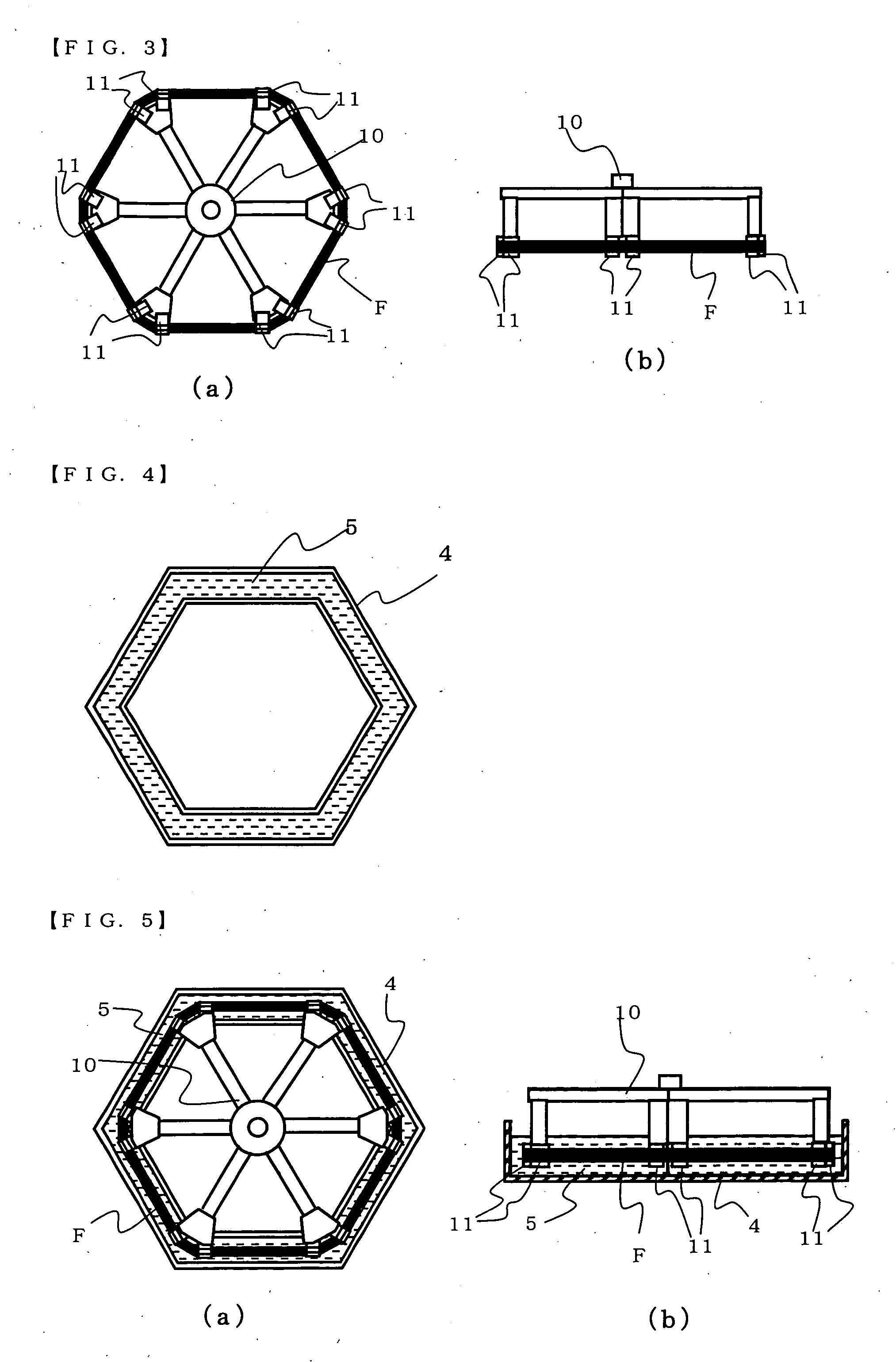
[0019] Next, the fiber bundle paralleled in a satisfactorily linear fashion, which has been prepared in this manner, passes to the embedding step; however, residual air is present inside the fiber bundle. The fiber bundle is therefore preferably allowed to stand in a satisfactorily paralleled state in the embedding container, and subjected to vacuum degassing. The pre-degassed embedding agent in a liquid or gaseous state is then filled into the container and impregnated into the fiber bundle with the fiber bundle surrounded by the embedding agent. Here, the embedding step is preferably carried out while evacuating the container with an exhauster as a vacuum apparatus under slightly negative pressure with respect to atmospheric pressure, to avoid residual air bubbles in the interior. This will prevent almost any air bubbles from forming in the embedded fiber bundle, thus allowing each of the individual filaments of the fiber bundle to be bound together. Thus, fiber bundles which are highly flexible and otherwise readily escape from the shaving blade when no binding force is acting on them are subjected to adequate shaving force which is transmitted when the shaving blade contacts each individual filament. By thinly shaving the embedded fiber bundle in this manner, therefore, it is possible to mass produce ultrashort-cut fibers having fiber lengths of 0.005-0.1 mm without miscutting.
[0021] It is preferred to avoid using overly thick fiber bundles which are resistant to infiltration by embedding agents such as water, and from which residual air in the fiber bundle interior is difficult to eliminate, and instead to embed numerous small fiber bundles or flat fiber bundles arranged in parallel. This will allow very effective removal of air bubbles included in the shaving material. When the water is frozen, air dissolved in the water will generate bubbles. Gentle heating is therefore performed with heating means above the cover of the freezing vessel in which freezing (embedding) is carried out. The freezing procedure with the freezing apparatus is preferably carried out in a controlled manner to avoid freezing of the water surface, maintaining reduced pressure above the water surface with a vacuum apparatus, in order to prevent residual air bubbles from the water.
[0022] The invention produces ultrashort-cut fibers by shaving in the manner described above, and the shaving means used may be a well-known machine tool such as a planing machine, slotting tool, planing / molding machine or miller, or a modified type thereof. The numerous prepared shaving materials are arranged in a densely parallel state by the process and apparatus described above. These may be again embedded in the embedding material in this aligned state to form an integrated block, which is used as the new shaving material and supplied to the machining bench. This will allow a large volume of ultrashort-cut fibers to be easily produced. Regardless of the means used for shaving of the shaving material, however, insulating means and / or cooling means are preferably provided to cool the holding means holding the shaving material, so that the embedding material forming part of the shaving material does not change from a solid state to a liquid or gaseous state. It will sometimes be preferable for the shaving blade to be cooled.

Problems solved by technology

As a result it was discovered that, even if not impossible, it is very difficult to properly cut the filament to a very short length of no greater than 0.1 mm at a satisfactory yield without miscutting.
However, this raised the problem of how to shave a fiber bundle consisting of numerous bound single thin individual filaments.

Method used

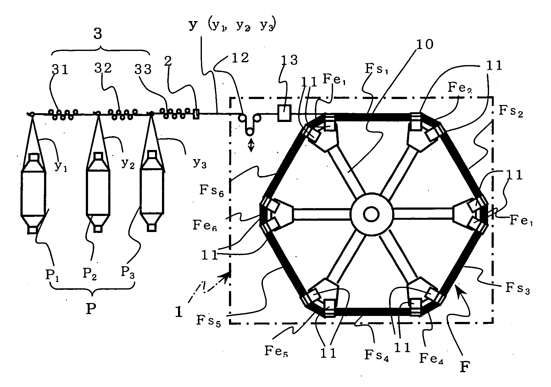
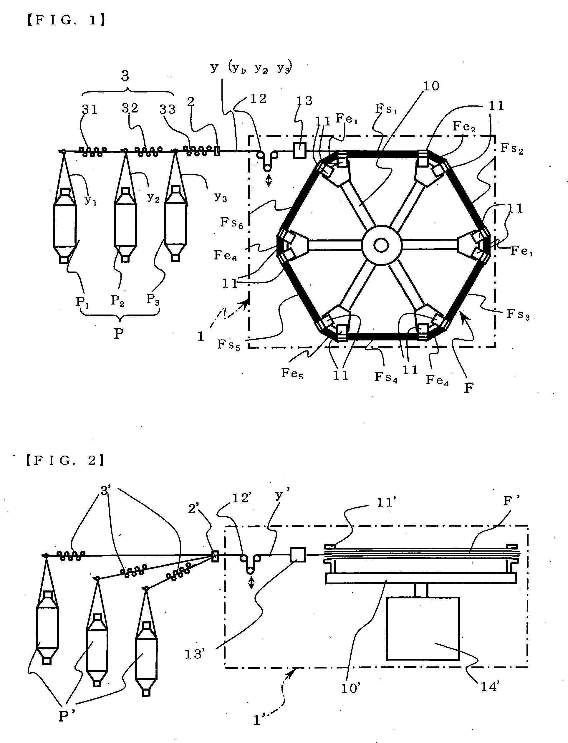

Image

  • Method and device for manufacturing extremely short fiber
  • Method and device for manufacturing extremely short fiber
  • Method and device for manufacturing extremely short fiber

Examples


first embodiment

[0046] According to the present invention, this problem is solved by, as a first embodiment, preparing one or more wound yarns which are formed by winding up the multifilament yarns composed of numerous individual filament groups. The yarns are drawn out from the wound yarns and lap wound on a winding reel such as, for example, a known coiling reel while applying a prescribed tension, to obtain a paralleled fiber bundle. Next, the fiber bundle obtained in this manner is embedded without being removed from the winding reel and while applying the same tension as during winding, so that the tension-applied fiber bundle is embedded and integrated in the embedding material.

second embodiment

[0047] Alternatively, as the invention, both ends of the fiber bundle, which was formed by lap winding the numerous yarns and was wound up in parallel, are completely bound with the same tension applied as during winding. In this case, the binding of both ends of the fiber bundle may be accomplished by wrapping the periphery of the aforementioned ends with adhesive tape to prevent the individual filament groups of the fiber bundle from moving freely, or by holding them with the strong force of a clamp. Also, an adhesive may be impregnated into only the end sections to adhesively anchor together the individual filaments of the fiber bundle.

[0048] In this case, unlike the first embodiment, removal from the reel can be accomplished by cutting the tape section anchoring both ends of the fiber bundle, or the adhesively anchored sections. For the removal, if a fixture such as a stretcher is mounted in order to hold both ends of the fiber bundle and allow the tension-applied state to be ob...


PUM

PropertyMeasurementUnit
lengthsaaaaaaaaaa
infiltration distanceaaaaaaaaaa
pressureaaaaaaaaaa

Abstract

It is an object to provide a process and an apparatus which allow stable production of ultrashort-cut fibers having fiber lengths of no greater than 0.1 mm while minimizing miscutting, the object being achieved by a process and apparatus whereby numerous individual filament groups are bound to form a fiber bundle, an embedding material which is solidified by cooling and gasified or liquefied by heating is gasified or liquefied, the fiber bundle is embedded with the gasified or liquefied embedding material, and the edge of the embedded fiber bundle is thinly shaved at a temperature at which the embedding material does not gasify or liquefy, to obtain ultrashort-cut fibers having cut fiber lengths of no greater than 1.0 mm.

Description

FIELD OF THE INVENTION [0001] The present invention relates to a process for production of ultrashort-cut fibers whereby numerous yarns composed of long individual filament groups are bundled to make a paralleled fiber bundle, and the fiber bundle is cut to produce ultrashort-cut fibers having a fiber length of no greater than 1 mm, as well as to an apparatus therefor. BACKGROUND ART [0002] Staple fibers with lengths of from several millimeters to several tens of millimeters have conventionally been obtained by bundling filaments made of thermoplastic synthetic positive such as polyesters or polyamides into a fiber bundle, and cutting the fiber bundle. The cutting apparatus used has been, for example, a roller cutter type fiber bundle cutting machine which winds the fiber bundle on a cutter roller provided with a plurality of cutting blades arranged in a radial fashion, and presses the fibers wound on the cutting blades against the cutting blades while continuously cutting them to t...

Claims


Application Information

Patent Timeline
Patent Type & Authority Applications(United States)
IPC IPC(8): D01G1/00
CPCD01G1/027D01G1/00
Inventor SHINDO, NAOHIKOSHIBAIKE, HAJIMEYONEDA, TAKUROKITAGISHI, YASUSHI
Owner TEJIN FIBERS LTD
Learn More