
Trailer hitch alignment device

Inactive Publication Date: 2006-10-12
GODWIN W LEE
View PDF29 Cites 15 Cited by
  • Summary
  • Abstract
  • Description
  • Claims
  • Application Information

AI Technical Summary

Benefits of technology

[0009] In the broadest sense, the invention is a trailer hitch alignment device that synergistically combines a laser level with an alignment mounting bracket, where the bracket, using a fastening means, provides a base on a vehicle for affixing the laser level to the vehicle. The laser level provides a laser beam, which is a visible guide for coupling the trailer to a fifth wheel hitch on the vehicle. The image created by the beam is preferably selectable, and is either a spot or a projected line. The spot has the advantage that it is more intense and easy to see in either day or night. The projected line has the advantage that as the distance from the laser increases, the length of the line increases. Therefore, a user can determine the distance to the trailer by the length of the line. The laser level also provides a means for confirming that the trailer, the vehicle, and the vehicle with the hitched trailer all have the proper weight distribution, as evidenced by their angle with respect to the road. The level has one or more bubble tubes for determining whether a surface is plumb and perpendicular to plumb (e.g., level). The alignment mounting bracket is preferably selected so that it can be quickly and reversibly fitted to the vehicle. In the case of a pickup truck, the bracket is sized so that it can fasten to the front wall of the truck bed. In the case of a tractor the bracket is suitably constructed to fasten to the rear of a cab. The fastening means is suitably selected to enable the laser level to be easily fastened to the alignment bracket, and to have the correct height and orientation. In the case of a pickup truck, the fifth wheel is mounted in the truck bed and the fifth wheel has a height such that the hitch clears the truck bed walls. When the alignment mounting bracket is mounted on the top ledge of the truck bed of the front wall, the laser beam has the desired height. Therefore, the fastening means desirably mounts the laser level substantially flush with the alignment mounting bracket. It is anticipated that the alignment mounting bracket could also be attached to the cab, the frame, or other positions on the front wall.

Problems solved by technology

While the prior art teaches the use of lasers to determine optical ranging, it fails to teach a relatively inexpensive device that can be quickly fitted to a vehicle, usually a pickup truck, having a fifth wheel hitch that is typically removable.
Furthermore, the prior art does not teach a device that can have multiple functions, both on and off the pickup truck, where the functions are all incorporated into one device.
Furthermore, the prior art does not teach a device that can be quickly removed from the vehicle, as it, like the fifth wheel, will not advantageously be permanently fixed to the vehicle.

Method used


Image

  • Trailer hitch alignment device
  • Trailer hitch alignment device
  • Trailer hitch alignment device

Examples


Embodiment Construction

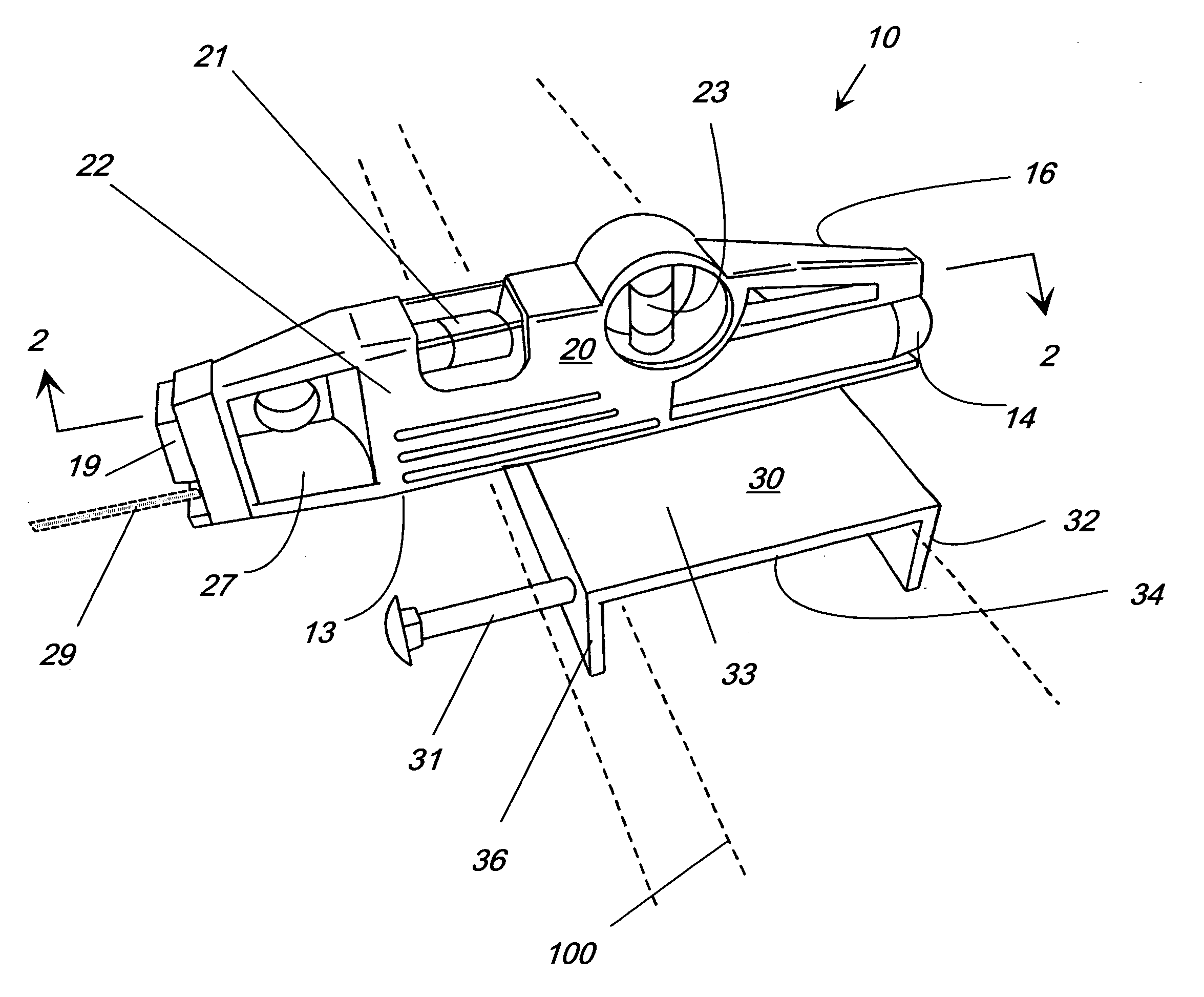
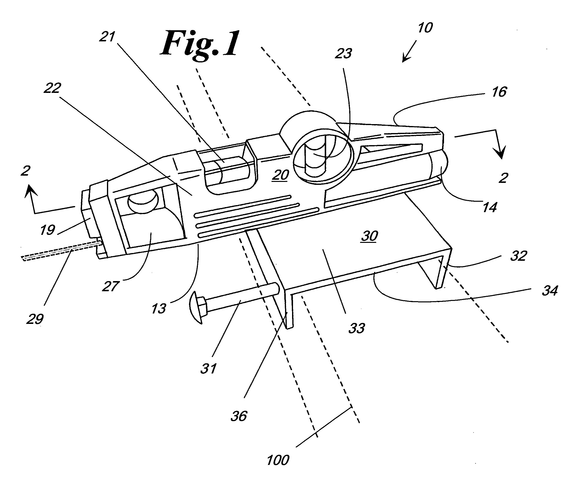
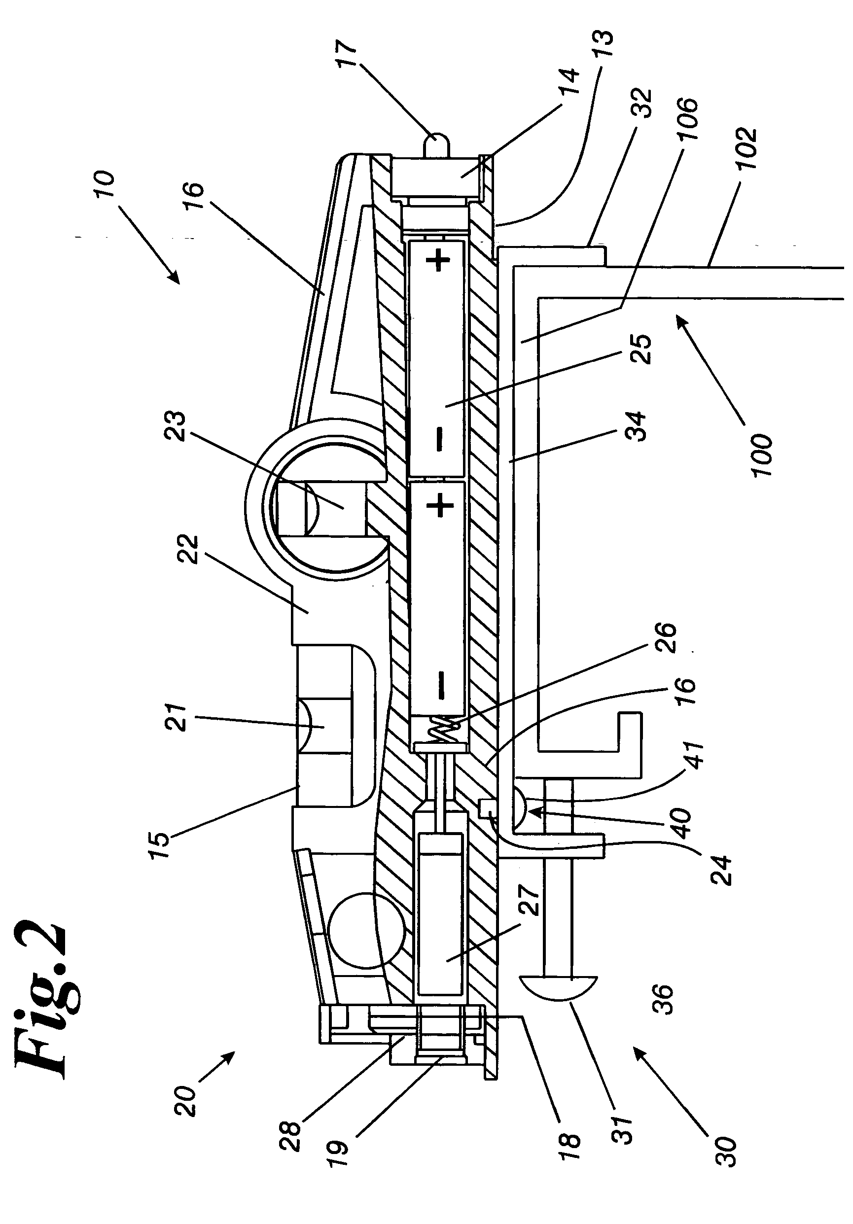
[0018] The invention is a trailer hitch alignment device 10 that synergistically combines a laser level 20 with an alignment mounting bracket 30, where the bracket, using a fastening means 40, provides a base on a vehicle 100 for affixing the laser level 20 to the vehicle 100. While a variety of laser levels are suitable, in a preferred embodiment the laser level has a frame that has good weathering characteristics and provides a protective housing for the laser. An example of a laser level having the desired properties is manufactured by Shinty Optic-Electric Instruments Co, Ltd. of China, Model Number TD20, wherein the level has an aluminum frame 22. An illustrated embodiment of the trailer hitch alignment device 10 is shown in FIG. 1. In the figure, the laser level 20 is shown affixed to the alignment mounting bracket 30. The fastening means 40, as shown in FIG. 2 and FIG. 3, is not visible in this view. The vehicle 100 is shown in ghost, and is not part of the disclosed trailer ...


PUM


Abstract

The invention is a trailer hitch alignment device that synergistically combines a laser level with an alignment mounting bracket, where the bracket, using a fastening means, provides a base on a vehicle for affixing the laser level to a vehicle. The laser level provides a laser beam which projects a lighted image that is a guide for coupling the trailer to a fifth wheel hitch on the vehicle. The level provides a means for confirming that the trailer, the vehicle, and the coupled trailer and vehicle all have the proper weight distribution as evidenced by their angle.

Description

BACKGROUND OF THE INVENTION [0001] 1) Field of the Invention [0002] The invention relates to a trailer hitch device, and more particularly to a trailer hitch alignments device for hitching a trailer to a vehicle fitted with a fifth wheel hitch, where the device is additionally a laser level. [0003] 2) Prior Art [0004] U.S. Pat. No. 6,176,505 B1 to Capik et al. teaches an optically guided alignment system. The invention teaches a trailer hitch alignment apparatus having a pair of light sources that emit different color light beams. The patent teaches that a single light source 24 can be aligned with a target 32, and discusses this in col. 5, lines 3-10. Referring to FIG. 3, alternate positions are shown for light source 22 (not shown) and 24. The light source is located adjacent to the rear 48 of cab section 50 of a pickup truck. Colored light beams 18, 20 are directed at a target location 32 at a point, which offers the driver of the tow vehicle 10 an unobstructed view of the target...

Claims


Application Information

Patent Timeline
IPC IPC(8): G01D21/00
CPCB60D1/36B62D53/12B62D53/08
Inventor GODWIN, W. LEE
Owner GODWIN W LEE
Learn More