Transportable building

a technology for transporting buildings and buildings, applied in the direction of building roofs, multi-purpose tools, construction, etc., can solve the problems of escorting, building or module requiring over-dimensional permits and escorting, and restricting the dimensional limit set by road transport authorities for ordinary unesco loads

Inactive Publication Date: 2006-10-12
PREBUILT
View PDF9 Cites 20 Cited by
  • Summary
  • Abstract
  • Description
  • Claims
  • Application Information

AI Technical Summary

Benefits of technology

[0058] For additional structural stability the fully erected building may be fastened down to concrete pads or footings, including where d

Problems solved by technology

A principal constraint in the design of manufactured housing is the strict dimensional limit set by road transport authorities for ordinary unescorted loads.
For example, while it is possible to transport new manufactured homes in Australia having a width of 5 m, and a maximum height of 4.8 m, this typically requires expensive permits, escorts and set routes, and regulations confine travel times to daylight hours.
If the manufactured housing is required to be transported overseas, it must comply with International Shipping Organisation (ISO) width dimensional limitations, which are more restrictive than the above referenced domestic limitations.
Thus, in Australia, manufactured housing is such that the buildings or modules either require over-dimensional permits and escorts, or are severely restricted in their design and size by the width dimensional limits.
Export housing, if attempted, is restricted by the ISO dimensional limitations.
Aside from the issue of additional cost, access of over-dimensional buildings to building sites is more restricted.
For example, over-dimensional buildings are typically not suitable for dual occupancy sites, provision of granny flats or house extensions, if the permanent location of the over-dimensional building is not easily accessible due to access width restrictions.
Further, over-dimensional building

Method used


Image

  • Transportable building
  • Transportable building
  • Transportable building

Examples


Embodiment Construction

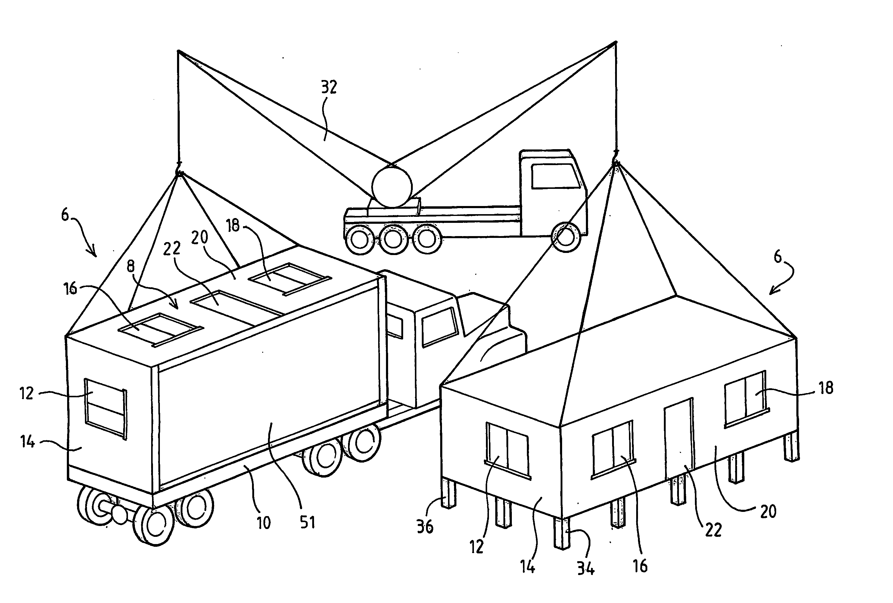
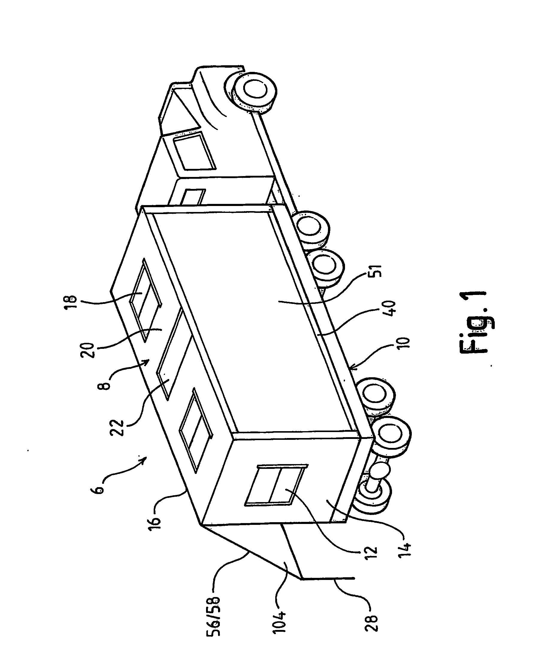
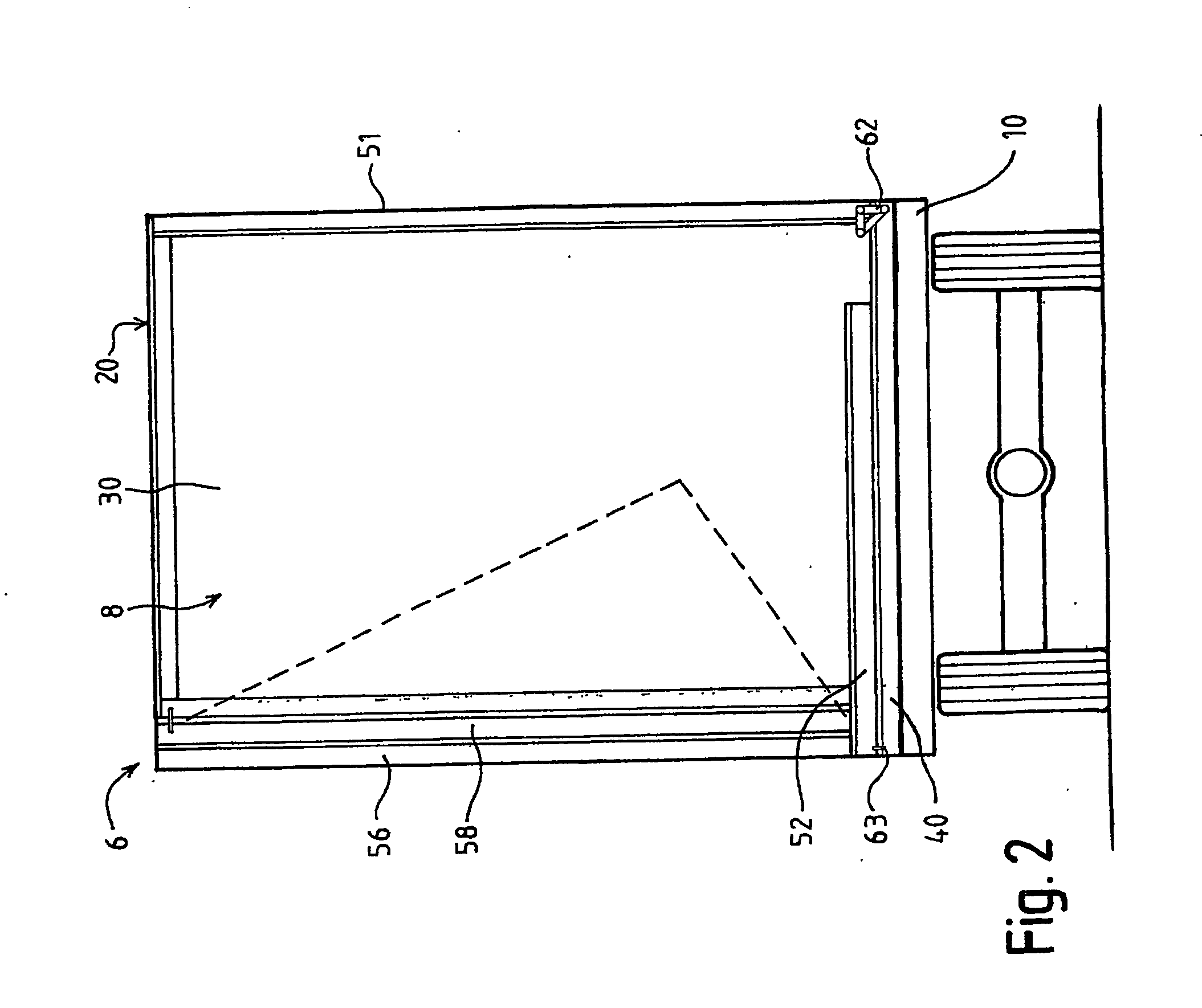
[0070] Referring to FIGS. 1 and 2, the transportable house 6, in its folded configuration on its side on a trailer 10, generally comprises an erected generally rectangular unit having the appearance and form of a box structure 8 about an enclosed space. A window 12 is formed in end walls 14 of the transportable house 6 and windows 16 and 18 are formed in sidewall 20. A door 22 is positioned approximately midway along the length of the sidewall 20. The transportable house 6 therefore comprises a pre-erected or pre-assembled unit comprising the end walls 14 and an external side wall 20. As will be explained in greater detail below, it also comprises floor panels 40, 51, roof panels 56 and 58, an external side wall 52, and an internal wall panel 54 (see FIG. 4) which is positioned opposite the side wall 20.

[0071] Although the roof panels 56 / 58 are shown in a partially open position in FIG. 1 for removal of materials from inside the transportable house 6, they are closed during transpo...


PUM


Abstract

A transportable building system including at least partially erecting a building, transporting the at least partially erected building (6) on its side to a building location, locating the at least partially erected building on a support at the building location, and orientating the at least partially erected building so that it is correctly orientated relative to its support. Further disclosed is a transportable building, including a first structural component (51; 58), a second structural component (40;56) and a hinge (68) coupling the first and second structural components whereby the second structural component is pivotable between a folded position and an unfolded erected position of the building. The hinge is reconfigurable to allow the second structural component to be relatively displaced away from the first structural component in the unfolded erected position of the second structural component.

Description

FIELD OF THE INVENTION [0001] The present invention relates to transportable buildings and in particular to manufactured or pre-built housing. BACKGROUND ART [0002] It is known to pre-construct housing or commercial building units at a base yard and subsequently transport them, either whole or in two or more modules, to a client's allotment. Such buildings are typically referred to as manufactured or pre-built housing and for reference purposes will subsequently be referred to as manufactured housing. [0003] A principal constraint in the design of manufactured housing is the strict dimensional limit set by road transport authorities for ordinary unescorted loads. For example, while it is possible to transport new manufactured homes in Australia having a width of 5 m, and a maximum height of 4.8 m, this typically requires expensive permits, escorts and set routes, and regulations confine travel times to daylight hours. In Australia and most countries, permits, escorts and / or set rout...

Claims


Application Information

Patent Timeline
IPC IPC(8): E04B1/346E04B1/343E04B1/344E04B1/348E04B7/16
CPCY10T16/5474E04B1/3442
Inventor NAPIER, DONALD STEWART
Owner PREBUILT
Why Eureka
Try Eureka