Wireless RF coil power supply

a power supply and wireless technology, applied in the field of magnetic resonance imaging, can solve the problems of standing waves and induced current in the coaxial cable, difficult management or maneuverability, and discomfort for imaging patients

Active Publication Date: 2006-10-12
GENERAL ELECTRIC CO
View PDF22 Cites 48 Cited by
  • Summary
  • Abstract
  • Description
  • Claims
  • Application Information

AI Technical Summary

Benefits of technology

[0007] The present invention is directed to a system and method overcoming the aforementioned problems by providing a wireless power supply arranged to provide power to operate an RF coil assembly. The wireless power supply operates without the use of a battery or a wired connection exte

Problems solved by technology

As the number of receive coils increases, the number of coaxial cables increases to match; thus, a large bundle of coaxial cables results that can become uncomfortable for an imaging patient when laid across the patient and difficult to manage or maneuver.
Further, interactions such as paral

Method used


Image

  • Wireless RF coil power supply
  • Wireless RF coil power supply
  • Wireless RF coil power supply

Examples


Embodiment Construction

[0018] The present invention will be described with respect to a whole body RF coil assembly of an MRI system having a transmit coil to create a B1 field and a receive coil used in conjunction with the transmit coil to detect or receive the signals from excited spins of nuclei in an imaged object. However, one skilled in the art will appreciate that the present invention is also applicable with local and surface coils.

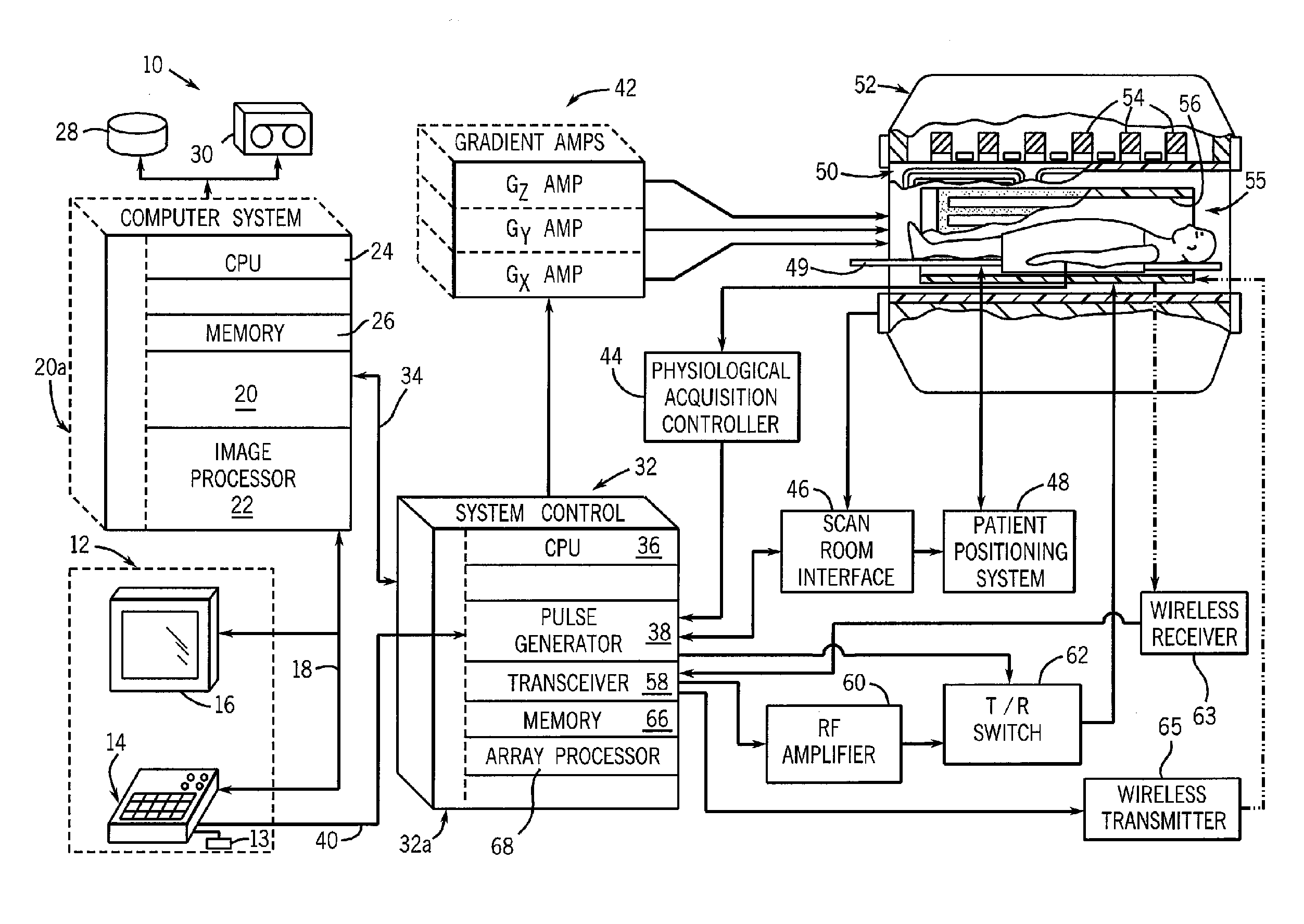
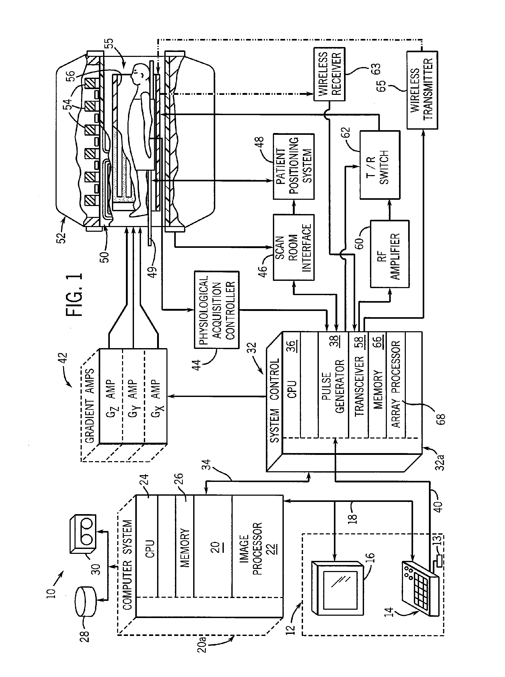
[0019] Referring to FIG. 1, the major components of a preferred magnetic resonance imaging (MRI) system 10 incorporating the present invention are shown. The operation of the system is controlled from an operator console 12 which includes a keyboard or other input device 13, a control panel 14, and a display screen 16. The console 12 communicates through a link 18 with a separate computer system 20 that enables an operator to control the production and display of images on the display screen 16. The computer system 20 includes a number of modules which communicate wit...


PUM


Abstract

A system wirelessly supplies electrical power to an RF coil and an analog-to-digital converter (ADC) for an MRI system. The system supplies power to at least operate the RF coil and ADC without the use of a battery and without use of a wired connection external to the bore of the magnet.

Description

BACKGROUND OF THE INVENTION [0001] The present invention relates generally to magnetic resonance imaging (MRI) and, more particularly, to a wireless RF coil power supply for an RF module configured to acquire MR signals from a receive coil of an MRI system. [0002] When a substance such as human tissue is subjected to a uniform magnetic field (polarizing field B0), the individual magnetic moments of the spins in the tissue attempt to align with this polarizing field, but precess about it in random order at their characteristic Larmor frequency. If the substance, or tissue, is subjected to an RF magnetic field (excitation field B1) which is in the x-y plane and which is near the Larmor frequency, the net aligned moment, or “longitudinal magnetization”, MZ, may be rotated, or “tipped”, into the x-y plane to produce a net transverse magnetic moment Mt. A signal is emitted by the excited spins after the excitation signal B1 is terminated and this signal may be received and processed to f...

Claims


Application Information

Patent Timeline
IPC IPC(8): G01V3/00
CPCG01R33/3692
Inventor BOSKAMP, EDDY B.WATKINS, RONALD D.KOSTE, GLEN P.
Owner GENERAL ELECTRIC CO
Why Eureka
Try Eureka