Speed bump mounted license plate camera system

Inactive Publication Date: 2006-10-12
FRIPP RICHARD D II +1
View PDF0 Cites 6 Cited by
  • Summary
  • Abstract
  • Description
  • Claims
  • Application Information

AI Technical Summary

Benefits of technology

[0014] An advantage of the present invention is that the mounting of the camera element at road surface level provides optimum camera angles for photographing license plates.
[0015] Another advantage of the present invention is that embedding the camera elements within a speed bump provides an unobtrusive surveillance location.
[0016] Still another advantage of the present invention is that the system is adapted to be quickly and removably mounted on a driving surface, making it suitable for use in temporary surveillance situations.
[0017] A further advantage of the present invention is that the speed bump components of the system can be inexpensively manufactured so that the system is broadly usable.
[0018] Yet another advantage of the present invention is that the speed bump mounted license plate camera system captures either or both front and rear license plate images, thus increasing the probability of positive identification.
[0019] Still another advantage of the present invention is that it psychologically induces drivers to position the vehicle in perfect position for good image capture of license plates.

Problems solved by technology

Pole and overhead mounted systems often provide poor angles of incidence.
Especially during night conditions, glare, vehicle lights and fog lamps interfere with the camera's image capture, and therefore require sophisticated light filtering devices.
Unfortunately, camera angles and weather and lighting conditions often conspire to obscure the license plates of the vehicles and make the identification difficult or impossible in many cases.

Method used


Image

  • Speed bump mounted license plate camera system
  • Speed bump mounted license plate camera system
  • Speed bump mounted license plate camera system

Examples


Embodiment Construction

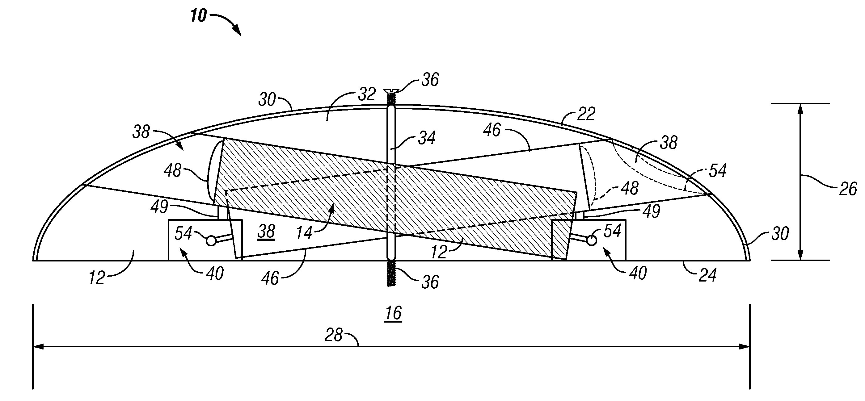
[0026] A preferred embodiment of the present invention is a speed bump mounted license plate camera system adapted to be placed on a driving surface and used for vehicle surveillance and identification. As illustrated in the various drawings herein, the preferred embodiment of the inventive system is designated by the general reference character 10.

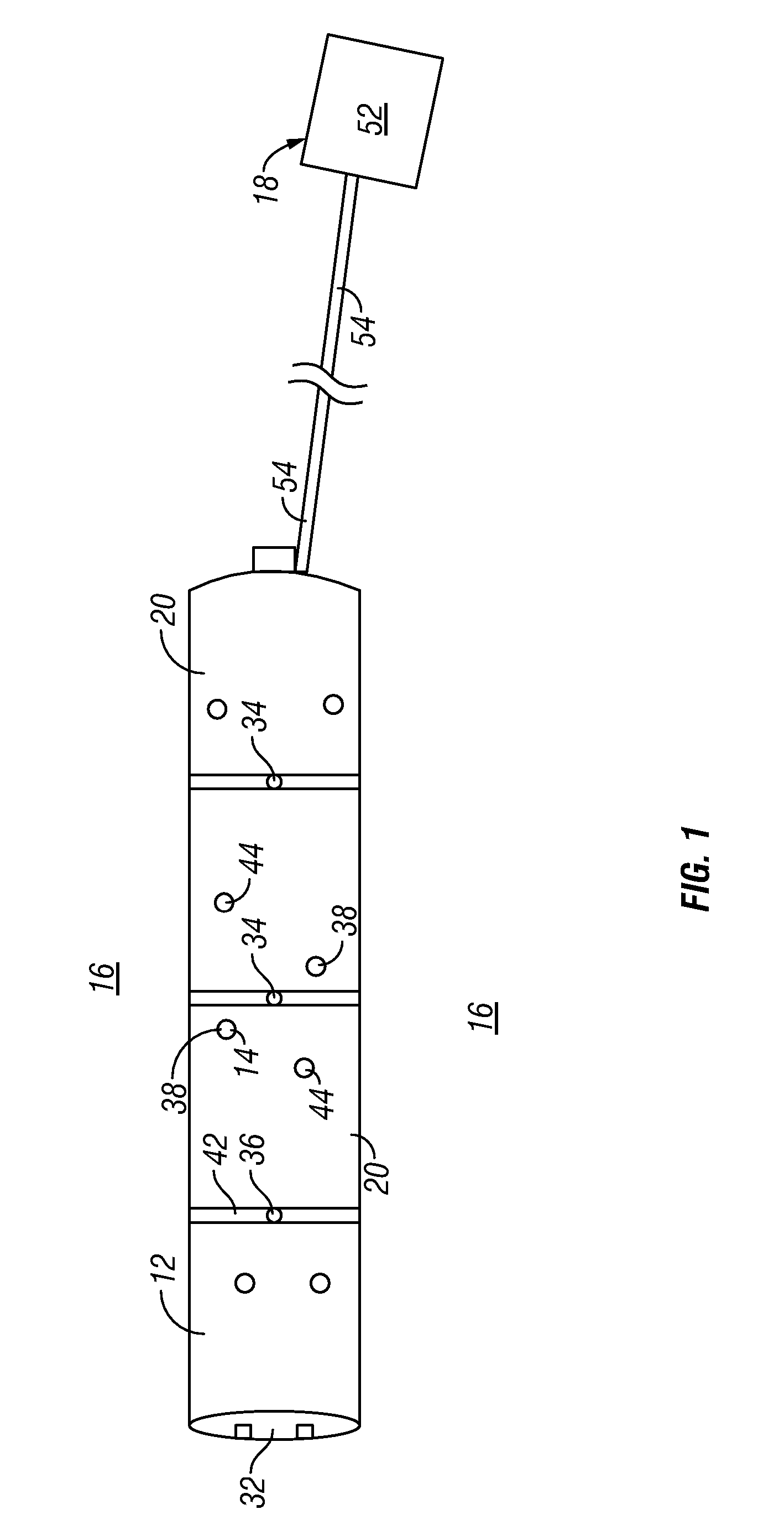
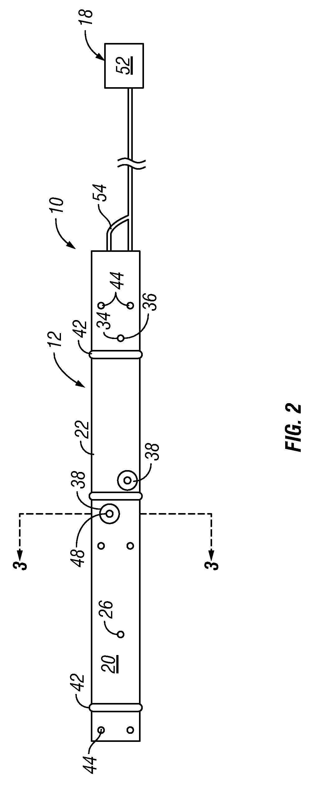
[0027] As illustrated in the views of FIGS. 1, 2 and 3, the preferred speed bump mounted license plate camera system (system) 10 includes a mounting subsystem 12 (speed bump) which supports and encloses an image subsystem 14 adapted to capture images. The speed bump 12 and the incorporated image subsystem 14 are adapted to be installed on a driving surface 16, such as a driveway or street. An external control subsystem 18 controls the operation of the image subsystem and records the images captured thereby.

[0028] The principal structure of the invention is provided by the speed bump 12 component which comprises the mounting subsystem. A...


PUM


Abstract

A speed bump camera mounting system (10) is provided for capture of photographic images or license places on passing vehicles. The system includes an elongated speed bump (12) for mounting on a driving surface (14). A pair of cameras (46) are mounted in angled image tubes (38) to deliver photographic (video) images to an external control system (18). Visual enhancement elements in the form of reflectors (44) and stripes (42) help a driver to center over the speed bump (20) during travel, thus aligning the license plate with the camera (46).

Description

[0001] The following claims priority from a provisional patent application Ser. No. 60 / 670,860, filed 12 Apr. 2005 by the same inventors.TECHNICAL FIELD [0002] The present invention relates generally to traffic control devices and more specifically to systems for identifying vehicles by photographing license plates. BACKGROUND ART [0003] There are many situations where it is desirable to be able to identify the vehicles which pass over particular portions of roadways, driveways and the like. Identification can be valuable for security purposes (such as entering, or leaving secure areas, parking garages and the like), for apprehension of scofflaws, such as on toll bridges and toll ways, and for crime prevention and incident resolution. [0004] One of best ways to identify vehicles is by the use of license plate photographs. Various methods have been used in the past to photograph vehicles at various stages, with the intent of obtaining positive identifications. Pole and overhead mount...

Claims


Application Information

Patent Timeline
IPC IPC(8): G08G1/054
CPCG08G1/054G08G1/0175
Inventor FRIPP, RICHARD D. IIFRIPP, SEAN L.
Owner FRIPP RICHARD D II
Why Eureka
Try Eureka