Substrate for a sensitive floor and method for displaying loads on one substrate

a technology of substrates and substrates, applied in the direction of instruments, building components, electric digital data processing, etc., can solve the problems of affecting the general cost of making a sensitive floor, particular structural arrangements are required, and the above described prior art suffers from certain drawbacks. , to achieve the effect of reducing the overall thickness of the sensitive floor

Inactive Publication Date: 2016-01-21
LUCCHESE CLAUDIO
View PDF5 Cites 0 Cited by
  • Summary
  • Abstract
  • Description
  • Claims
  • Application Information

AI Technical Summary

Benefits of technology

[0038]considerably reducing the overall thickness of sensitive floors;
[0039]allowing any

Problems solved by technology

The above described prior art suffers from certain drawbacks.
A first drawback is that detailed and prompt detection requires a network with a great number of knots, and hence sensors, such that the entire surface of the floor, or at least most of it, can sense the loads acting thereupon without leaving insensitive areas.
This requires the use of both a multitude of sensors and a proportional number of transmission cables, which largely affects the general cost for making a sensitive floor.
Another drawback is that particular structural arrangements are required between the bottom surfaces of the tiles and the contact surfaces of sensors for load stresses to be transferred in conditions as close as possible to the actual value.
A further problem is that the large amount of transmission cables that form the networks creates particularly bulky connection terminals, which cannot be easily concealed within the overall floor thickness.
Yet another problem is that, if one of the transmission cables is accidentally broken, the whole network becomes inactive and the floor will be no longer abl

Method used


Image

  • Substrate for a sensitive floor and method for displaying loads on one substrate
  • Substrate for a sensitive floor and method for displaying loads on one substrate
  • Substrate for a sensitive floor and method for displaying loads on one substrate

Examples


first embodiment

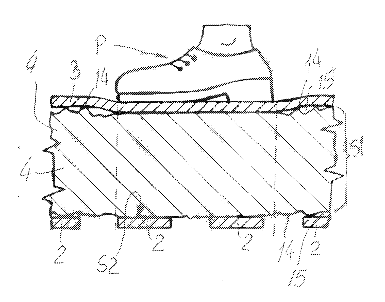
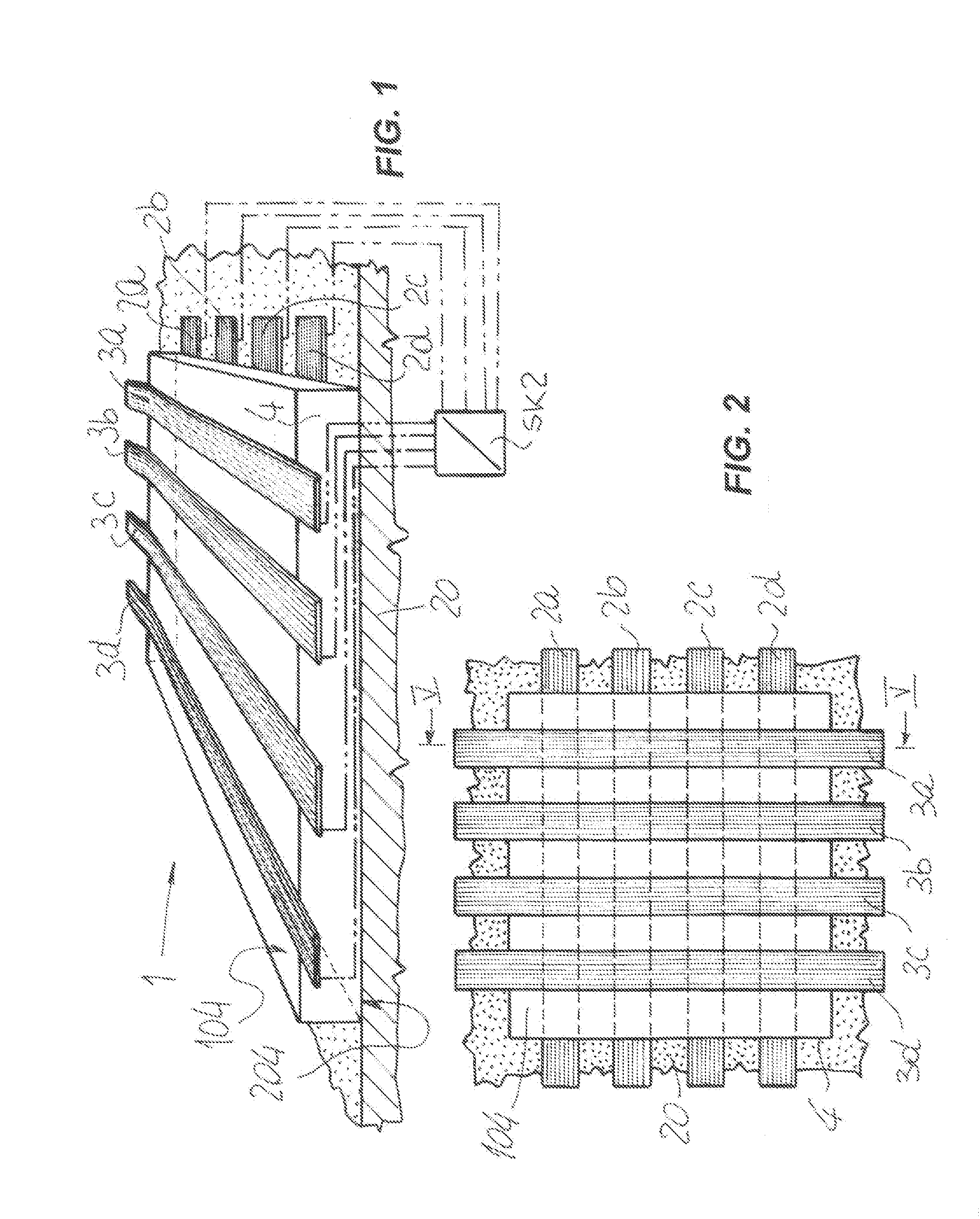
[0050]Referring now to FIGS. 1-3, numeral 1 designates a substrate, or a module to make a larger substrate, for making a sensitive floor, i.e. a floor that can continuously sense the stresses acting thereupon, and send the signals generated by these stresses to a computer 11 that has a program for promptly and continuously displaying the changes of these stresses on a monitor, in graphics forms.

[0051]The substrate 1 is preferably provided in the form of a flexible sheath, and may have a custom perimeter, or be divided into two or more modular elements that can be joined together side-by-side to form a large complete substrate.

[0052]The substrate 1 comprises a first frame of sensing means, which are preferably but without limitation made of parallel thin strips of a high-conductivity material, such as aluminum, having a first common orientation and referenced 2a-2d, whose number may change as needed.

[0053]The substrate 1 also comprises a second frame of sensing means, which is also p...

second embodiment

[0068]FIGS. 4, 7 and 8 show a substrate, referenced 50, for making a sensitive floor according to the invention.

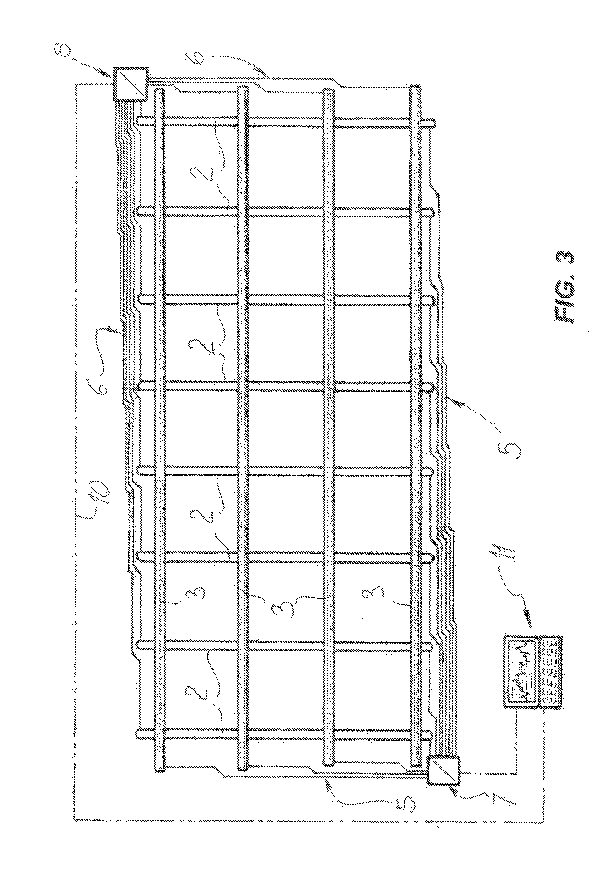
[0069]Like in the above described embodiment, the substrate 50 comprises a first frame of strips, generally referenced 2, and a second frame of strips, generally referenced 3, both made of aluminum, and hence having a high conductivity, which are arranged in perpendicular relationship.

[0070]Nevertheless, unlike the previous embodiment, both frames of strips 2 and 3 lie on a common face 54 of the sheet 4, typically the face designed to face upwards when the substrate 50 has been laid.

[0071]In this case, in order to prevent contact interferences between the strips 2 and 3 at their intersection points, their upward surfaces are both coated with a sheet of insulating material, typically paper or plastic, referenced 55, as best schematically shown in FIGS. 7 and 8.

[0072]Conversely, the opposite surfaces of the strips 2 and 3, i.e. those facing the face 54, have no protection, l...


PUM


Abstract

As substrate for making a sensitive floor includes a first frame made of high-conductivity sensing elements having a first orientation; a second frame made of high-conductivity sensing elements, which is adapted to be laid on the first frame and has a second orientation, other than the first orientation, the second frame forming a support layer for floor finishing products; and an element made of a conductive material, which includes an elastically compressible layer having a thickness, two opposite faces contacting the first and second frames, and an electric resistor whose resistance is proportional to the thickness.

Description

FIELD OF THE INVENTION[0001]The invention relates to a substrate for making a sensitive floor and a method for continuous sensing and display of loads on the substrate, which can be generally used for detecting both static and dynamic stresses on the floor, and transducing them into continuous or substantially continuous signals transmitted to a continuous electronic display device.BACKGROUND ART[0002]So-called “sensitive floors” have been known, which can detect the presence of moving or stationary people and things thereupon.[0003]These floors generally consist of a network of pressure signal carrying cables or bands, with sensors located at their knots.[0004]This network typically extends directly on the base foundation of a surface that is designed to become a floor, the latter being finished by usual finishing products, typically in the form of tiles or slabs of various types, laid on the sensors, such that as they are walked upon, they press on the sensors which in turn genera...

Claims


Application Information

Patent Timeline
IPC IPC(8): E04B5/43E04B5/46G01N27/04H05K7/18
CPCE04B5/43G01N27/041H05K7/18E04B5/46E04F15/107E04F15/16G06F3/045
Inventor LUCCHESE, CLAUDIOCUCCHIARA, RITALOMBARDI, MARTINOPIERACCI, AUGUSTOSANTINELLI, PAOLOVEZZANI, ROBERTO
Owner LUCCHESE CLAUDIO
Why Eureka
Try Eureka