Method of driving shift register, gate driver, and display device having the same

a shift register and gate driver technology, applied in the field of shift registers, can solve the problems of difficult to discharge the first output signal goutb>1/b> through the second transistor mb>2, and the first output signal goutb>1/b> cannot be discharged quickly, so as to improve the reliability of the gate driver and the display devi

Active Publication Date: 2006-10-12
LG DISPLAY CO LTD
View PDF4 Cites 61 Cited by
  • Summary
  • Abstract
  • Description
  • Claims
  • Application Information

AI Technical Summary

Benefits of technology

[0021] An object of the present invention is to provide a method of driving a s...

Problems solved by technology

However, when the first shift register SRC1 is reset by the second output signal GOUT2 of the second shift register SRC2, the first output signal GOUT1 of the first shift register SRC1 is not discharged easily to a low state.
However, since the second transistor M2 is in the turned-off state, it is difficult to discharge the first output signal GOUT1 through the second transistor M2.
Thus, the first output signal GOUT1 cannot be discharged quickly.
Con...

Method used


Image

  • Method of driving shift register, gate driver, and display device having the same
  • Method of driving shift register, gate driver, and display device having the same
  • Method of driving shift register, gate driver, and display device having the same

Examples


Embodiment Construction

[0036] Reference will now be made in detail to the preferred embodiments of the present invention, examples of which are illustrated in the accompanying drawings. Wherever possible, the same reference numbers will be used throughout the drawings to refer to the same or like parts.

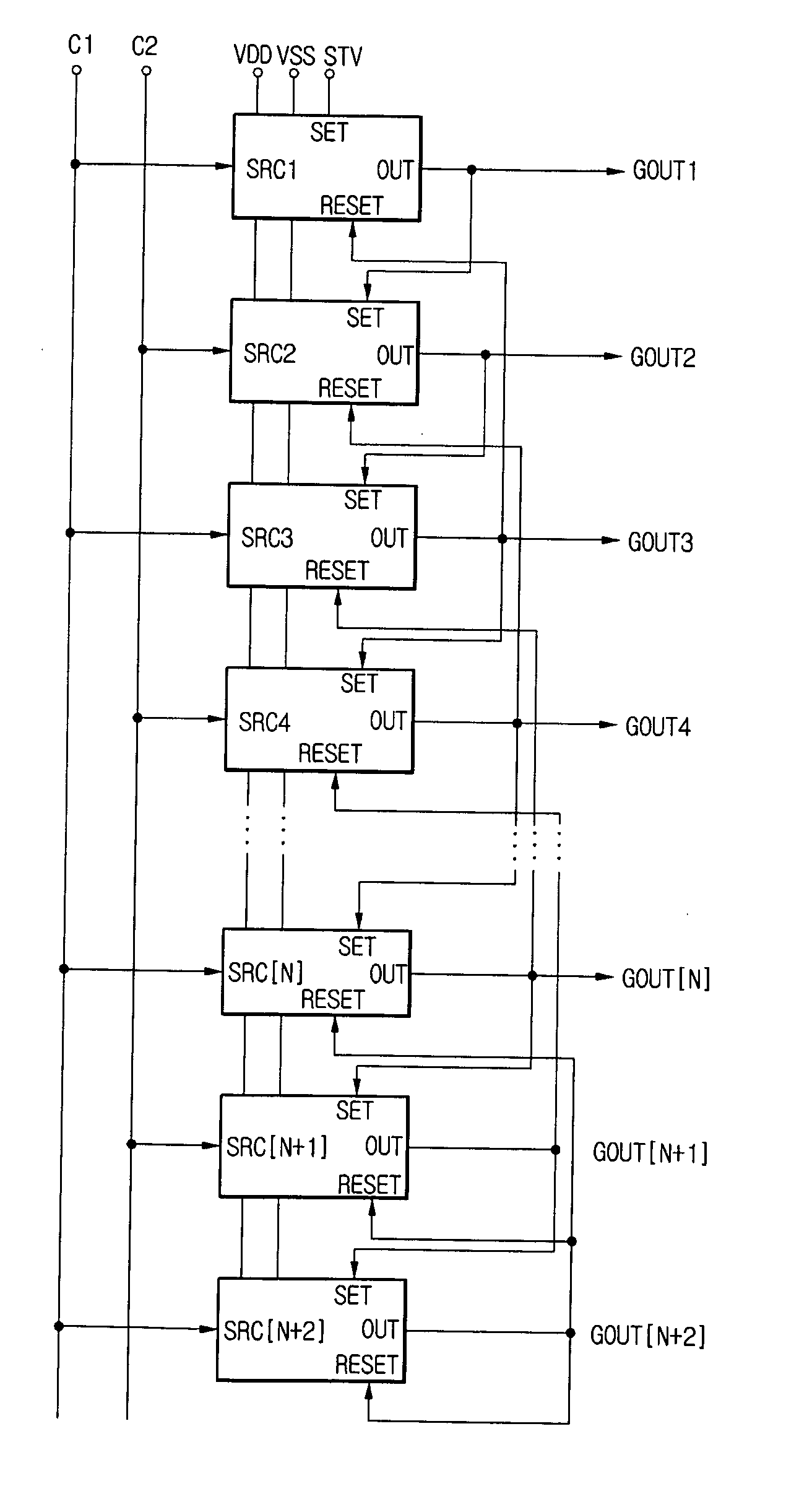
[0037]FIG. 5 is a block diagram of a gate driver according to an embodiment of the present invention. Referring to FIG. 5, the gate driver includes n number of shift registers SRC1 to SRC[N] and dummy shift registers SRC[N+1] and SRC[N+2].

[0038] A first clock C1 and a second clock C2 is input to the shift registers SRC1 to SRC[N+2]. A first power supply voltage VSS of a low state and a second power supply voltage VDD of a high state are supplied to the shift registers SRC1 to SRC[N+2]. The shift registers SRC1 to SRC[N+2] are connected in cascade manner. That is, the first shift register SRC1 is driven by a pulse start signal STV and outputs a first output signal GOUT1. The second shift register SRC2 is d...


PUM


Abstract

A gate driver, comprises a plurality of shift registers configured to output signals sequentially such that an Nth shift register is reset by an output signal of an (N+2)th shift register, wherein last, second last and third last shift registers are reset by a last output signal of the last shift register.

Description

[0001] This application claims the benefit of the Korean Patent Application No. 2005-029839 filed on Apr. 11, 2005, which is hereby incorporated by reference. BACKGROUND OF THE INVENTION [0002] 1. Field of the Invention [0003] The present invention relates to a shift register, and more particularly, to a method of driving a shift register, a gate driver, and a display device having the same with greater reliability. [0004] 2. Discussion of the Related Art [0005] A display device for displaying an image by controlling the pixels arranged in a matrix has been widely used. Examples of the display devices are a liquid crystal display (LCD) device, an organic light emitting diode (OLED) device, etc. Such a display device includes a display panel having the pixels arranged in a matrix, a gate driver for scanning pixels line by line, and a data driver for supplying an image data. [0006] Recently, a display device having a gate driver and / or a data driver embedded on a display panel has bee...

Claims


Application Information

Patent Timeline
IPC IPC(8): G09G3/36
CPCG09G3/20G11C19/28G09G2310/0267G09G3/3677B43K5/1881B43K7/08
Inventor JANG, YONG HOKIM, BINNCHO, HYUNG NYUCK
Owner LG DISPLAY CO LTD
Why Eureka
Try Eureka