Motorized blend alignment tool

a technology of blend alignment and motorized blend, which is applied in the direction of manufacturing tools, metal-working feeding devices, instruments, etc., can solve the problems of low manufacturing and economic cost, and achieve the effects of low economic and manufacturing cost, efficient calibration and/or adjustment, and facilitating calibration and/or adjustmen

Active Publication Date: 2006-10-12
BARCO NV
View PDF9 Cites 14 Cited by
  • Summary
  • Abstract
  • Description
  • Claims
  • Application Information

AI Technical Summary

Benefits of technology

[0007] It is an object of the present invention to provide methods and systems, e.g. tools, for efficiently calibrating and / or adjusting and / or optimizing the blending of sub-images in a multi-channel projection system. It is also an object of the present invention to provide methods and systems, e.g. tools, allowing more facilitated calibrating and / or adjusting and / or optimizing blending of sub-images in a multi-channel projection system. Still another object of this invention is to provide methods and systems, e.g. tools, for calibrating and / or adjusting and / or optimizing the blending of sub-images in a multi-channel projection system which have a low economical and manufacturing cost. Yet another object of the present invention is to provide a method and systems, e.g. a tool, for calibrating and / or adjusting and / or optimizing the blending of sub-images fully applicable by a single person. It is also an object of the present invention to provide projection systems adapted for applying methods and systems for calibrating and / or adjusting and / or optimizing the blending of sub-images of such systems.

Problems solved by technology

The latter results in a lower manufacturing and economical cost.

Method used


Image

  • Motorized blend alignment tool
  • Motorized blend alignment tool
  • Motorized blend alignment tool

Examples


first embodiment

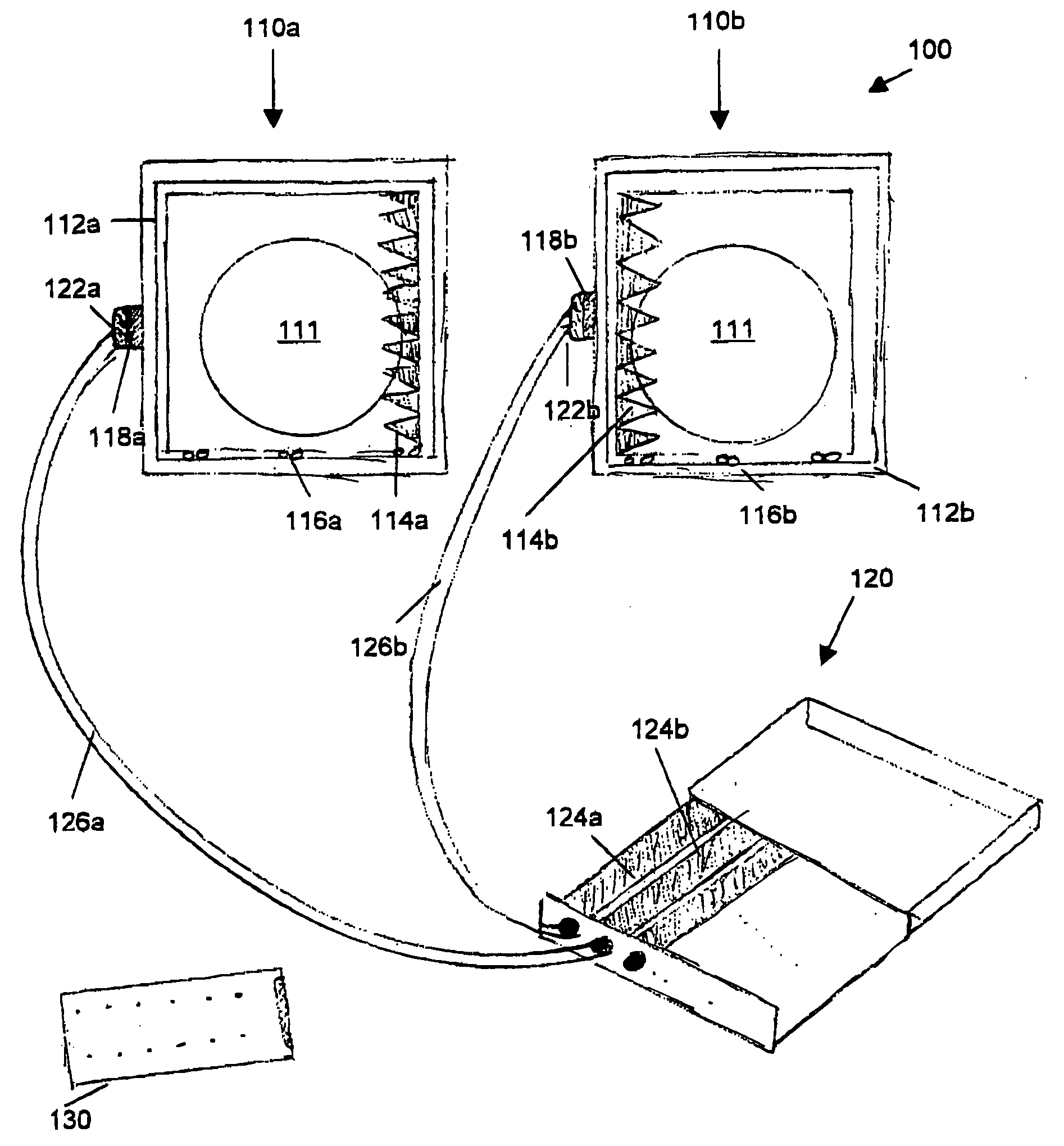
[0047] In a first embodiment, the present invention relates to a blending method and blending tool for calibrating and / or optimizing and / or adjusting of the blending of sub-images in a multi-channel projection system. This calibrating, optimizing and / or adjusting can be performed in an automated way. The latter does not per se mean that no intervention is needed for controlling the blending means, but it implies that driving means, such as e.g. a DC motor or a stepper motor, are used instead of a complete manual control of the blending means. An example of an automated blending tool according to an embodiment of the present embodiment is shown in FIG. 3. A blending tool 100 according to the present invention comprises a plurality of adjustable optical blending means 110a, 110b which are adapted to each be mounted on a channel of a multi-channel projection system and a removable controlling means 120 for controlling the plurality of adjustable optical blending means 110a, 110b. The r...

third embodiment

[0066] In a third embodiment, the present invention relates to methods for adjusting the blending in a multi-channel projection system comprising adjustable optical blending means as described in the previous embodiments or suitable for comprising these adjustable optical blending means. In FIG. 9 a flow chart of a method for adjusting the blending of a m×n projection system according to the present invention is shown. Such a method 500 typically comprises the following steps.

[0067] Depending on whether the blending means 110a, 110b are already provided, in a first step 502 adjustable optical blending means 110a, 110b as described in the previous embodiments are mounted to each channel of the multi-channel projection system. This step is avoided when the system already comprises such blending means 110a, 110b, e.g. provided during fabrication or during a previous optimization of the blending in the system.

[0068] In a second step 504, the method comprises projecting a test signal. S...


PUM

PropertyMeasurementUnit
optical blendingaaaaaaaaaa
optical axisaaaaaaaaaa
areaaaaaaaaaaa

Abstract

A blending tool is described for blending sub-images of a multi-channel projection system comprising a plurality of projectors. The blending device typically has a number of adjustable optical blending means which each are adapted to be mounted on a projector of said multi-channel projection system. Using a removable controlling means allows automated controlling of at least one of the adjustable optical blending means, or a blending component thereof. The removable controlling means therefore has engaging means for temporary engaging the removable controlling means to the adjustable blending means. In a preferred version, the blending tool allows remote control of the adjustable blending means such that blending can be performed from the viewing side of the projection system, even for rear-projection systems. Furthermore a method for blending and projection systems adapted for being blended using the blending tool are provided.

Description

TECHNICAL FIELD OF THE INVENTION [0001] The present invention relates to the field of multi-channel display systems and image projectors. More particularly, the present invention relates to blending tools and methods for creating a seamless composite image in multi-channel display systems based on a number of projectors. BACKGROUND OF THE INVENTION [0002] Multi-channel arrangement projection systems are projection systems projecting a composite image which is subdivided in two or more sub-images each projected by means of a separate projector element, the sub-images being tiled in such a way that together they form a bigger image. The advantage of this method of projection is that the field of view can be increased while maintaining a high image resolution and that a system with small footprint can be used for projecting large images. This kind of large field of view projection systems serve different broad areas of application: electronic presentations, e.g. for business, education...

Claims


Application Information

Patent Timeline
Patent Type & Authority Applications(United States)
IPC IPC(8): G03B21/26
CPCG03B21/14H04N9/3147G03B37/04G03B21/13G02B27/1066B21D11/10B21D43/027B21D53/16F16B21/186
Inventor MATTHYS, GEERTVICTOR BRUWIER, LUDO FRANCOIS
Owner BARCO NV
Why Eureka
Try Eureka