Image processing system, image processing device, dot data processing device, and method and program product therefor

a technology of image data and image processing system, applied in the field of image processing system, can solve the problems of limiting the effectiveness of the aforementioned technology in speeding up the output of images, requiring more time for image processing, so as to achieve rapid output of images and high picture quality

Inactive Publication Date: 2006-10-12
SEIKO EPSON CORP
View PDF9 Cites 4 Cited by
  • Summary
  • Abstract
  • Description
  • Claims
  • Application Information

AI Technical Summary

Benefits of technology

[0010] In view of the drawbacks of the existing technology, it is an object of the present invention to provide a simple image processing technology whereby image processing and data transfer can be performed at high speed, while maintaining satisfactory output picture quality.

Problems solved by technology

Naturally, when the number of pixels making up an image is increased, more time is required for image processing, making it difficult to output images quickly.
However, even where image processing can be performed quickly, time is required for transfer of the original image data, and for transfer of the processed image data, so there is a limit to the effectiveness of the aforementioned technology in speeding up the output of images.
In such cases, it is not possible to perform image processing using an image processing device with high processing capability, such as a personal computer.
However, where there are too few classes of encoding correspondence relationship, it may prove difficult to adequate prevent a pattern from occurring.
First, where it is possible to produce multiple types of dots, the data representing the dot on-off state for each pixel on a per-dot type basis will necessarily entail a large amount of data, and transfer of this data will be time-consuming.
Additionally, a larger number of dot types tends to result in more time being needed to determine the dot on-off states, making it difficult to output images rapidly.

Method used


Image

  • Image processing system, image processing device, dot data processing device, and method and program product therefor
  • Image processing system, image processing device, dot data processing device, and method and program product therefor
  • Image processing system, image processing device, dot data processing device, and method and program product therefor

Examples


first embodiment

C. Overview of Image Printing Process of

[0142] C-1. Basic Principle by which Pixel Location is Determinable from Count Data:

[0143] C-2. Multilevel Halftoning Result Value Creation Process of First Embodiment

[0144] C-3. Classification Number Determination Process:

[0145] C-4. Multilevel Halftoning Table

[0146] C-5 Data Format of Multilevel Halftoning Result Values

[0147] C-6. Dot On-off State Determination Process of First Embodiment:

[0148] C-7. Alternative Embodiments of First Embodiment:

second embodiment

D. Second Embodiment

[0149] D-1. Overview of Image Printing Process of Second Embodiment:

[0150] D-2. Multilevel Halftoning Result Value Creation Process of Second Embodiment: [0151] D-2-1. Large / Medium / Small Dot Count Determination Process Using Dither Method [0152] D-2-2. Specifics of Multilevel Halftoning Result Value Creation Process of Second Embodiment:

[0153] D-3. Dot On-off State Determination Process of Second Embodiment:

third embodiment

E.

[0154] E-1. Multilevel Halftoning Result Value Creation Process of Third Embodiment:

[0155] E-2. Dot On-off State Determination Process of Third Embodiment:

[0156] E-3. Multilevel Halftoning Table Setup Process of Third Embodiment:

E-4. Modifications of Third Embodiment:

[0157] A. Overview of the Embodiments:

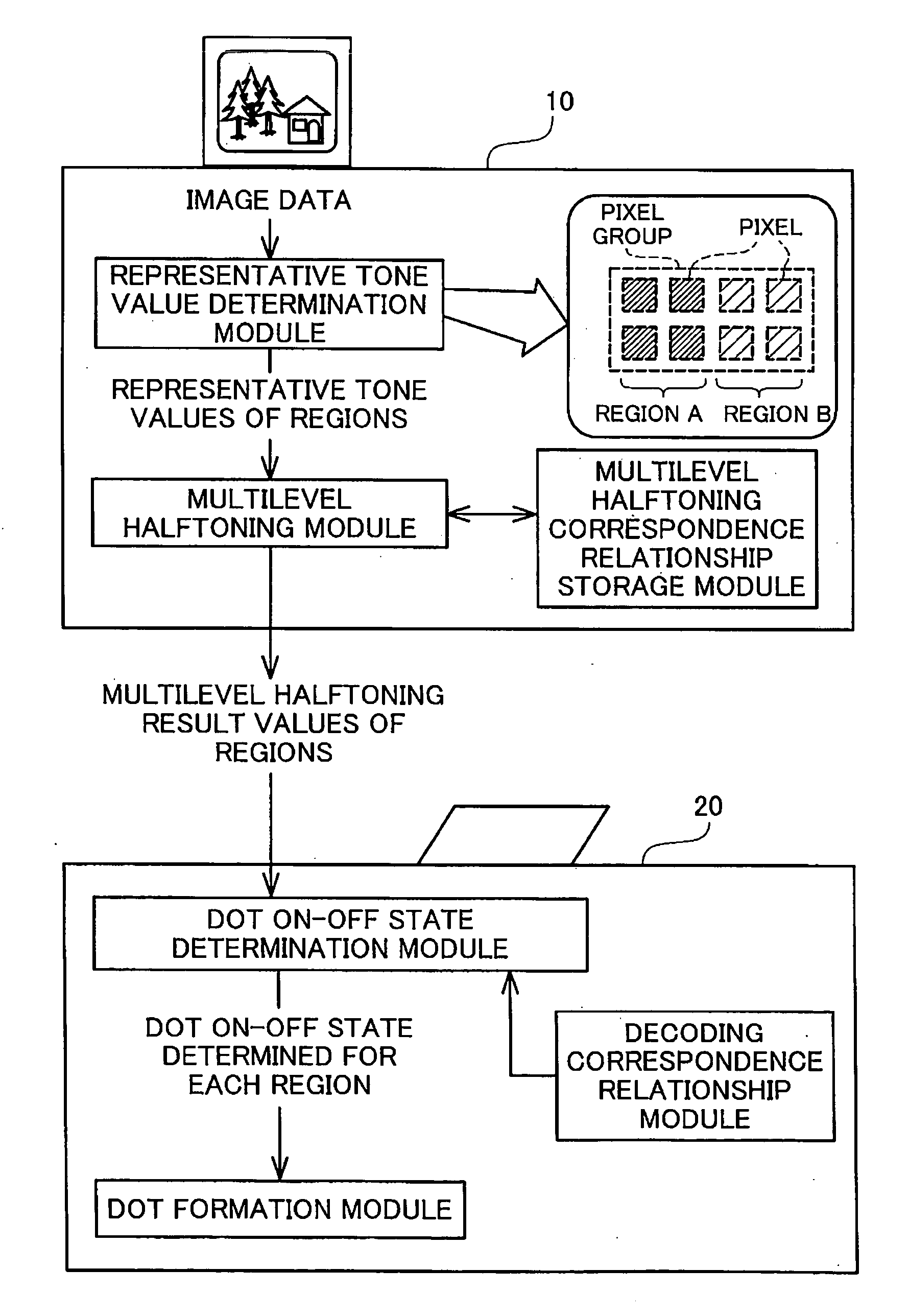
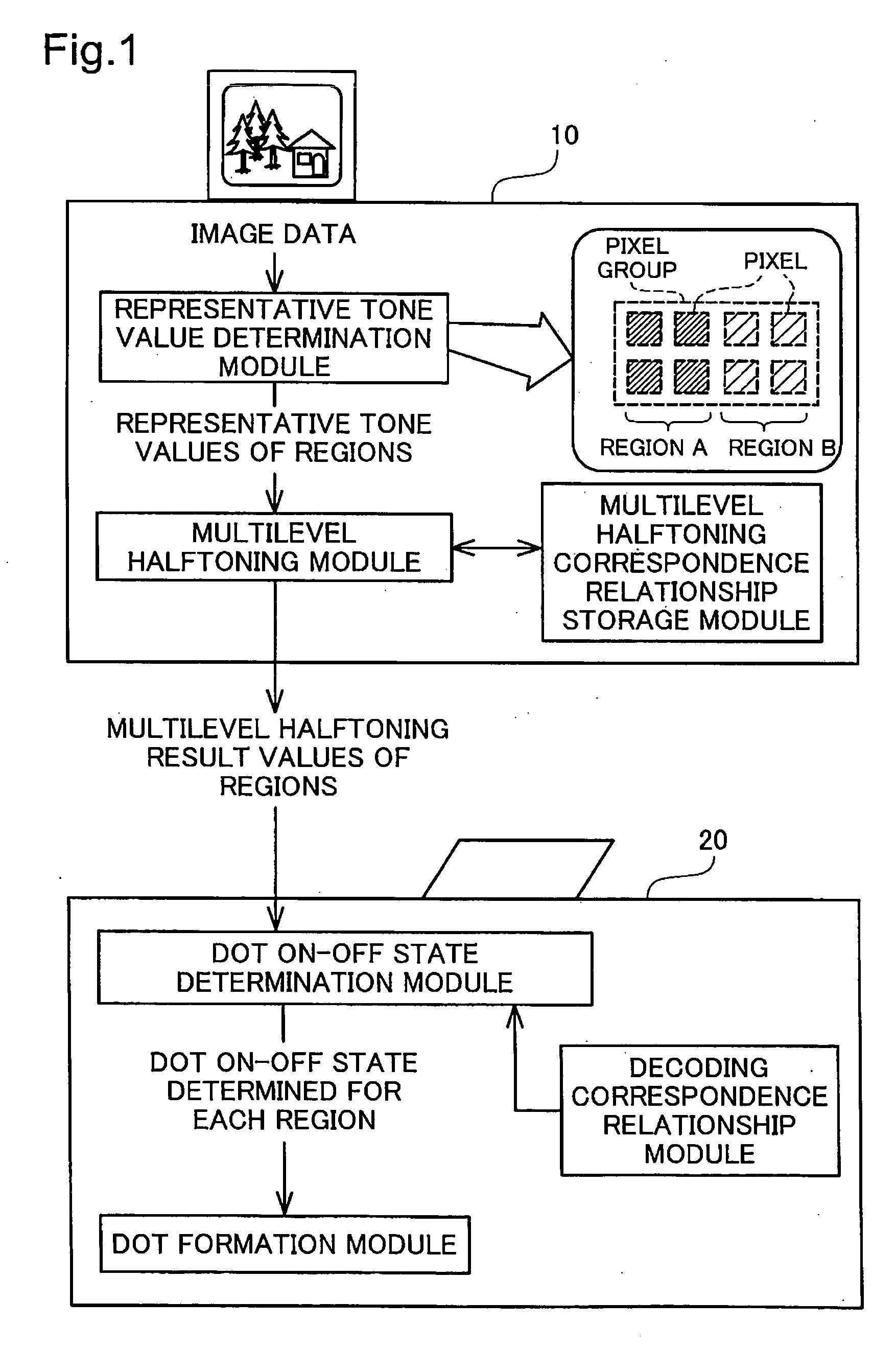
[0158] Before proceeding on to a detailed description of the embodiments, an overview of the embodiments will be described. FIG. 1 is an explanatory diagram depicting an overview of the embodiments, taking the example of a printing system. The printing system comprises a computer 10 as the image processing device, and a printer 20 as the image output device; when a specific program is loaded and executed by the computer 10, the computer 10 and the printer 20 function as a whole as an integrated image processing system. The printer 20 prints images by forming dots on a print medium. The computer 10 performs specific image processing of image data for images to be printed, and...


PUM


Abstract

Sets of multiple pixels are grouped into pixel groups, and on the basis of tone value distribution in each pixel group, it is decided whether to divide the pixel group. For pixel groups that are not divided, a representative tone value is determined for the pixel group, and for pixel groups that are divided, a representative tone value is determined for each region created by the division. Next, from multilevel halftoning result values derived by multilevel halftoning of the representative tone values, the dot on-off state is determined for each pixel in the pixel groups, and the image is output. At this time, for divided pixel groups, the dot on-off state is determined for each pixel in the regions, based on the multilevel halftoning result value for each region. With multilevel halftoning result values, data creation and transfer can be performed rapidly. Additionally, since the dot on-off state can be determined for each pixel in a pixel group even in instances where the pixel group has a tone value distribution, images of high picture quality can be output rapidly by unit of a simple process.

Description

CLAIM OF PRIORITY [0001] The present application claims priority from Japanese application P2004-189869 filed on Jun. 28, 2004, the content of which is hereby incorporated by reference into this application. BACKGROUND [0002] 1. Field of the Invention [0003] The present invention relates to technology for outputting images based on image data, and in particular relates to technology for outputting images by performing specific image processing on image data to generate appropriate dot density. [0004] 2. Description of the Related Art [0005] Image output devices for outputting images by forming dots on various types of output media such as a printing medium or liquid crystal display are widely used as output devices for various types of imaging devices. With these image output devices, images are handled in a form divided into minute regions known as pixels, and the dots are formed on these pixels. Where dots are formed on pixels, on the individual pixel level, it is of course only p...

Claims


Application Information

Patent Timeline
Patent Type & Authority Applications(United States)
IPC IPC(8): H04N1/40
CPCH04N1/4105
Inventor KAKUTANI, TOSHIAKI
Owner SEIKO EPSON CORP
Why Eureka
Try Eureka