
Image processing device and image processing method

a technology of image processing and image, applied in the field of image processing device and computer-readable storage medium, can solve the problems of increasing processing time, unable to achieve high image quality for two or more overlapping images, and complex process of quantization of cyan and magenta into three values, so as to achieve quick and easy execution of pseudo halftone process, facilitate the determination of the correction area, and generate the effect of correction valu

Inactive Publication Date: 2006-10-12
CANON KK
View PDF16 Cites 32 Cited by
  • Summary
  • Abstract
  • Description
  • Claims
  • Application Information

AI Technical Summary

Benefits of technology

[0017] An object of the present invention is to provide an image processing method and device which can both quickly and easily execute a pseudo halftone process with a large number of output gray levels and which can always execute the pseudo halftone process in the same manner regardless of the number of output gray scales, as well as computer-readable storage medium on which an image processing program for executing the image processing method is recorded.
[0027] The present invention can both quickly and easily execute a pseudo halftone process with a large number of output gray scales and can always execute the pseudo halftone process in the same manner regardless of the number of output gray scales.
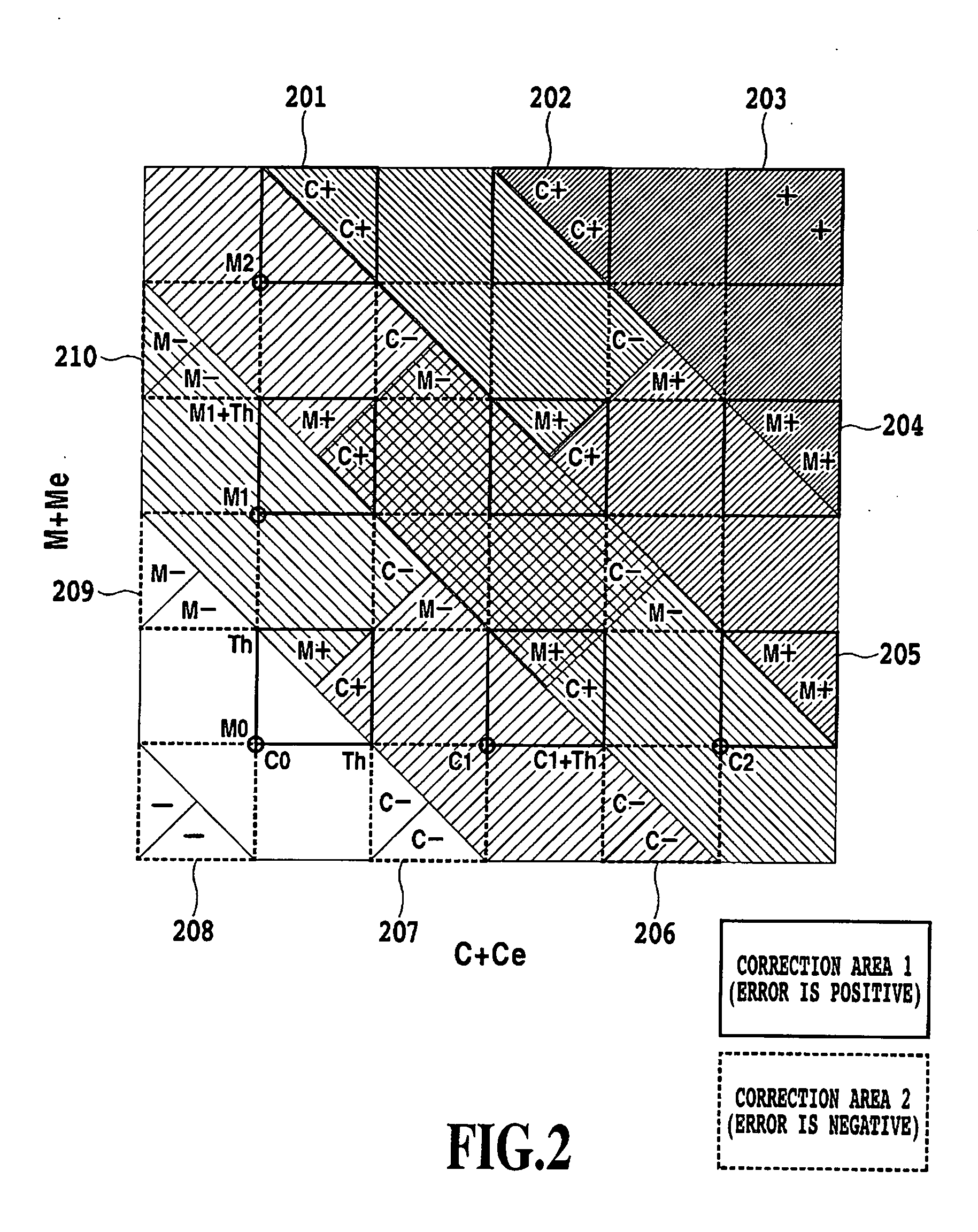
[0028] The present invention also determines a correction area on the basis of the match between the signs of the quantization errors and the comparison of the sum of the quantization errors with the threshold. This facilitates the determination of the correction area and the generation of a correction value. The present invention also determines the priorities of the planes to be corrected on the basis of the numbers of quantization error signs for neighborhood pixels. This enables dots to be efficiently distributed using a small memory capacity. If the quantization errors in the neighborhood pixels have the same sign, the connections between dots in the same plane can be excluded by using random numbers to determine the priorities. These processes are independent of the number of quantization levels. This enables the present method to be easily expanded so as to be applicable to error diffusion for N values. The present method can be easily expanded so as to be applicable to three or more planes as described above.

Problems solved by technology

That is, the error diffusion method distributes an error resulting from a conversion of multivalued image data into binary image data, to substantially zero accumulative errors in the colors of the entire image.
This enables each color to appear excellent but may fail to achieve a high image quality for two or more overlapping images.
However, with the conventional image processing method, an increase in the number of gray scales consistently complicates the above judgment expressions, thus increasing the time required for processing.
Thus, the mere quantization of cyan and magenta into three values is a complicated process.
Quantization into more gray scales requires a further complicated process.

Method used


Image

  • Image processing device and image processing method
  • Image processing device and image processing method
  • Image processing device and image processing method

Examples


first embodiment

[0038] Embodiments of the present invention will be described below with reference to the drawings.

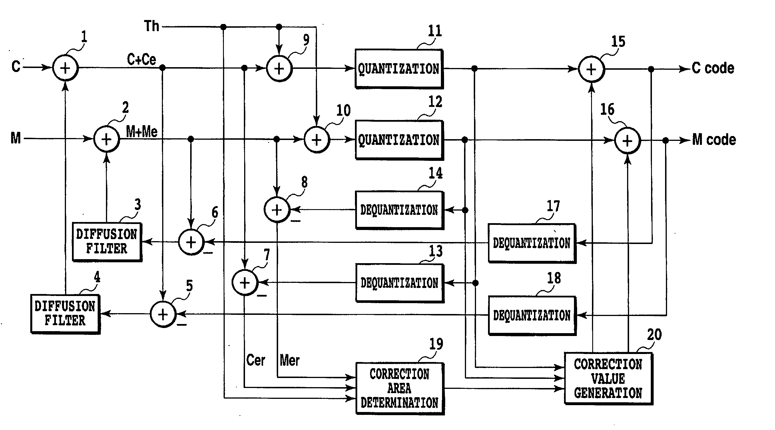
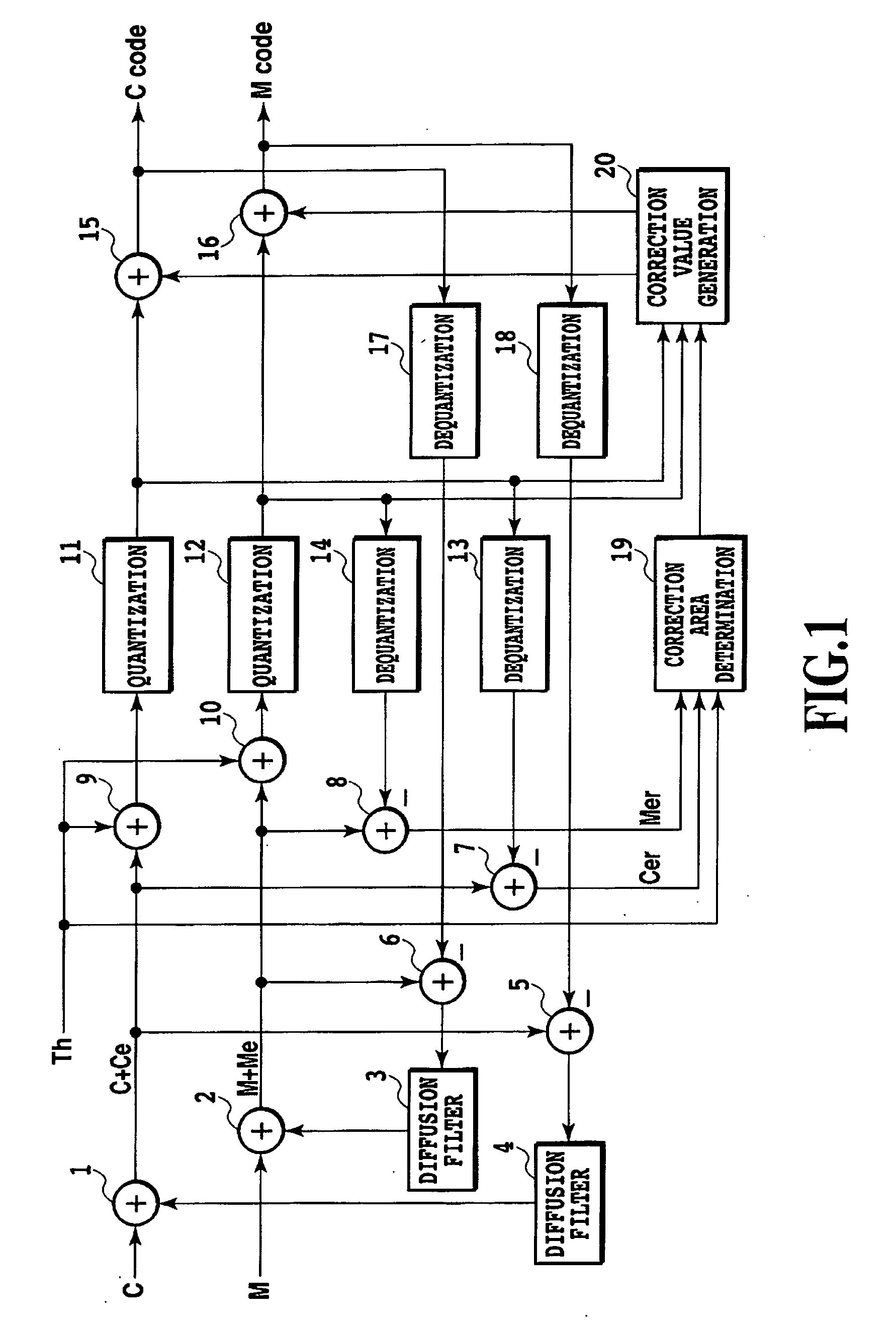
[0039]FIG. 1 is a block diagram illustrating an image processing device in accordance with the first embodiment of the present invention. For convenience, two planes for cyan and magenta are processed. That is, planes for color image data in accordance with the present embodiment are color planes for output colors into which the color image data is discomposed. The present embodiment uses four color planes for C, M, Y, and K. However, the color planes are not limited to these four colors.

[0040] In FIG. 1, reference numerals 1, 2, 9, 10, 15, and 16 denote adders, and reference numerals 3 and 4 denote diffusion filters. Reference numerals 5, 6, 7, and 8 denote subtractors, and reference numerals 11 and 12 denote quantizers. Reference numerals 13, 14, 17, and 18 denote dequantizers, and reference numerals 19 and 20 denotes a correction area determining section and a correction value gen...

second embodiment

[0057]FIG. 3 is a block diagram illustrating the configuration of an image processing device in accordance with a second embodiment of the present invention. In the figure, reference numeral 21 denotes a threshold generating section. Only the differences from the first embodiment will be described below.

[0058] In spite of the sequential variation of the threshold by the threshold generating section 21, the second embodiment enables the overlapping of color planes to be controlled on the basis of determinations similar to those described in the first embodiment. In the present embodiment, the planes in color image data correspond to the data on colors resulting from color separation.

[0059] The threshold generating section 21 varies the threshold in order to eliminate “sweep-up” or “texture” that may degrade image quality in error diffusion. The “sweep-up” appears markedly at an edge adjacent to an input value close to a quantization representative value. A known method thus hastens...

third embodiment

[0066]FIG. 5 is a block diagram illustrating the configuration of an image processing device in accordance with a third embodiment of the present invention. In the figure, reference numeral 22 denotes a correction area determining section, and reference numerals 23 and 24 denote threshold generating sections. Only the differences from the second embodiment will be described below.

[0067] In spite of the sequential variation of the threshold by the threshold generating sections 23 and 24, the third embodiment enables the overlapping of color planes to be controlled on the basis of determinations similar to those described in the first embodiment.

[0068] As described above, if a common threshold is used for a plurality of color planes, eliminating “sweep-up” without any problem is very difficult. Specifically, if the threshold is varied to eliminate the “sweep-up” from a certain color plane, overcompensation (sticking of dots to the edge or the like) may occur in other color planes, t...


PUM


Abstract

The present invention provides an image processing method and device which can both quickly and easily execute a pseudo halftone process with a large number of output gray levels and which can always execute the pseudo halftone process in the same manner regardless of the number of output gray scales. The present invention provides an image processing device that executes a pseudo halftone process on multivalued image data comprising a plurality of planes, the device including a component executing quantization and outputting for each of the plurality of density components, a component determining a correction value on the basis of a sign of a quantization error in each plane and a comparison of a sum of the quantization errors with a predetermined threshold, and a component correcting a value of the quantization output using the correction value and diffusing the quantization value.

Description

BACKGROUND OF THE INVENTION [0001] 1. Field of the Invention [0002] The present invention relates to an image processing device and a computer-readable storage medium on which an image processing program is recorded. More specifically, the present invention relates to an image processing method and device which quantizes input data into binary or multivalued data while maintaining the difference between an input image density and an output image density by an error diffusion method, as well as a computer-readable storage medium on which an image processing program for executing the image processing method is recorded. [0003] 2. Description of the Related Art [0004] A pseudo halftone process conventionally represents input multivalued image data as binary image data or multivalued image data at a level lower than that of the input multivalued image data. The pseudo halftone process is a technique for converting an image represented at multivalued gray scales into an image represented...

Claims


Application Information

Patent Timeline
IPC IPC(8): G06K9/00
CPCH04N1/52
Inventor ISHIKAWA, HISASHI
Owner CANON KK
Learn More