Leg portion training device

a training device and leg portion technology, applied in the field of equipment, can solve the problem of limited direction of applying load, and achieve the effect of effective contributing to the prevention of lifestyle-related diseases

Inactive Publication Date: 2006-10-12
PANASONIC CORP
View PDF25 Cites 80 Cited by
  • Summary
  • Abstract
  • Description
  • Claims
  • Application Information

AI Technical Summary

Benefits of technology

[0006] In view of the above problems, a primary concern of the present invention is to provide a leg training equipment for allowing a user having knee pain to perform an exercise for causing a muscle contraction at a femoral region, thereby effectively contributing to lifestyle-related diseases prevention.

Problems solved by technology

This means that a direction of applying the load can be limited in a direction of connecting the center of knee and the second toe.

Method used


Image

  • Leg portion training device
  • Leg portion training device
  • Leg portion training device

Examples


first embodiment

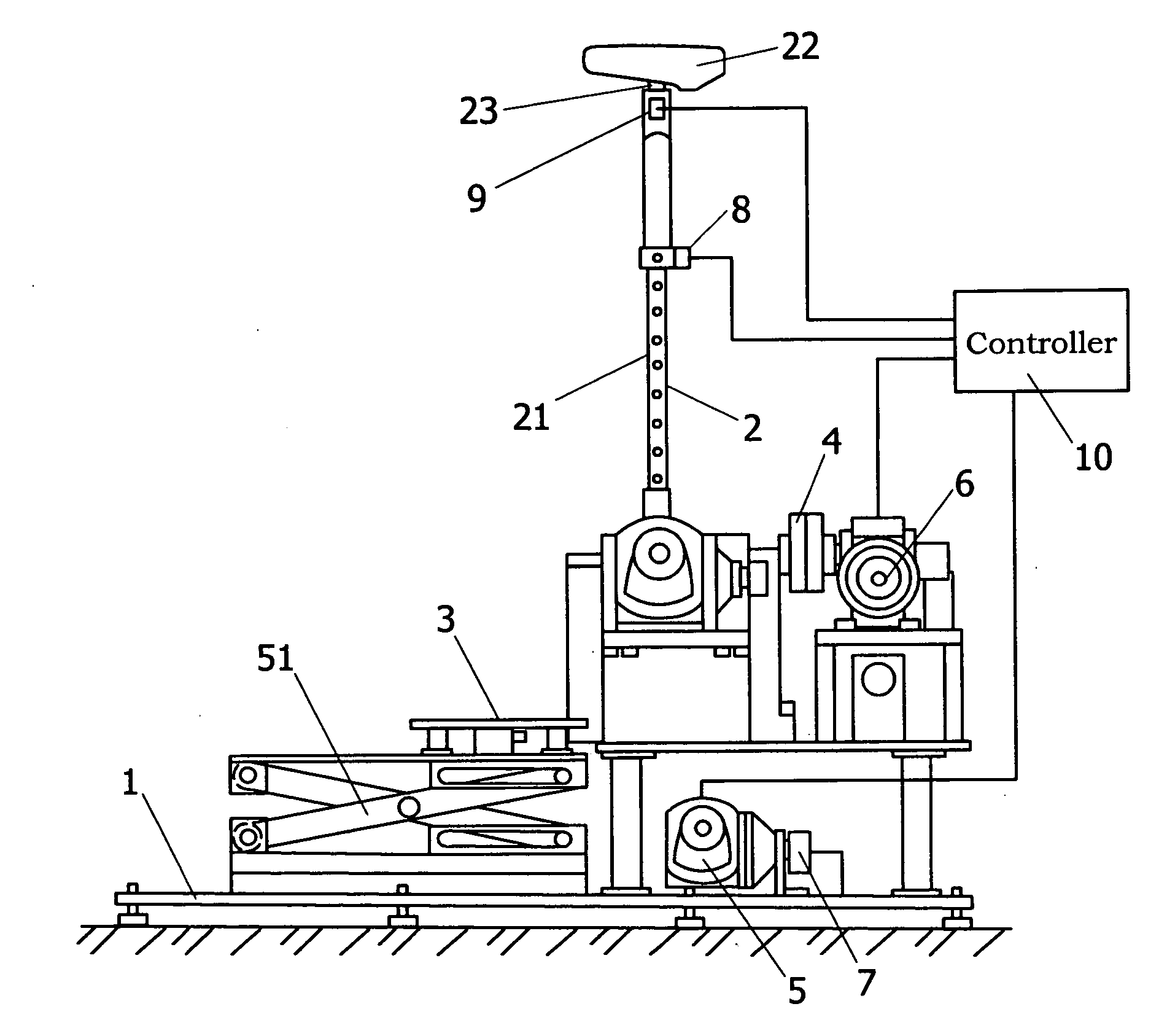
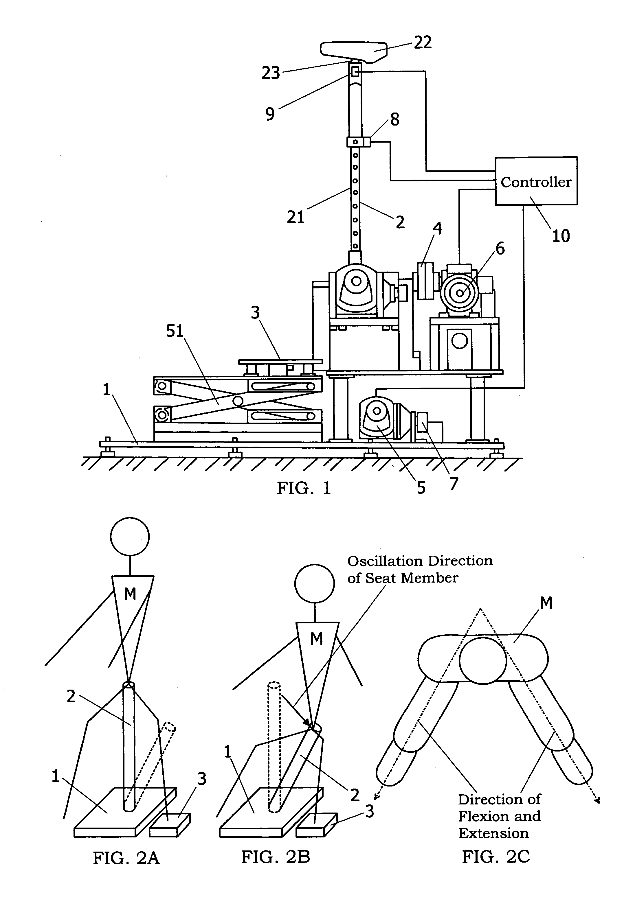
[0063] As shown in FIG. 1, the leg training equipment of this embodiment has a base 1 fixed on a floor surface, a seat member 2 for supporting a hip of a user, and a pair of footplates 3, on which the user's feet are placed. The seat member 2 and the footplates 3 are mounted on the base 1 through a coupling mechanism 4, 5. Motors 6, 7 are respectively connected as drive units to the coupling mechanisms 4, 5, and controlled by a controller 10. The motor 7 is provided to each of the footplates 3.

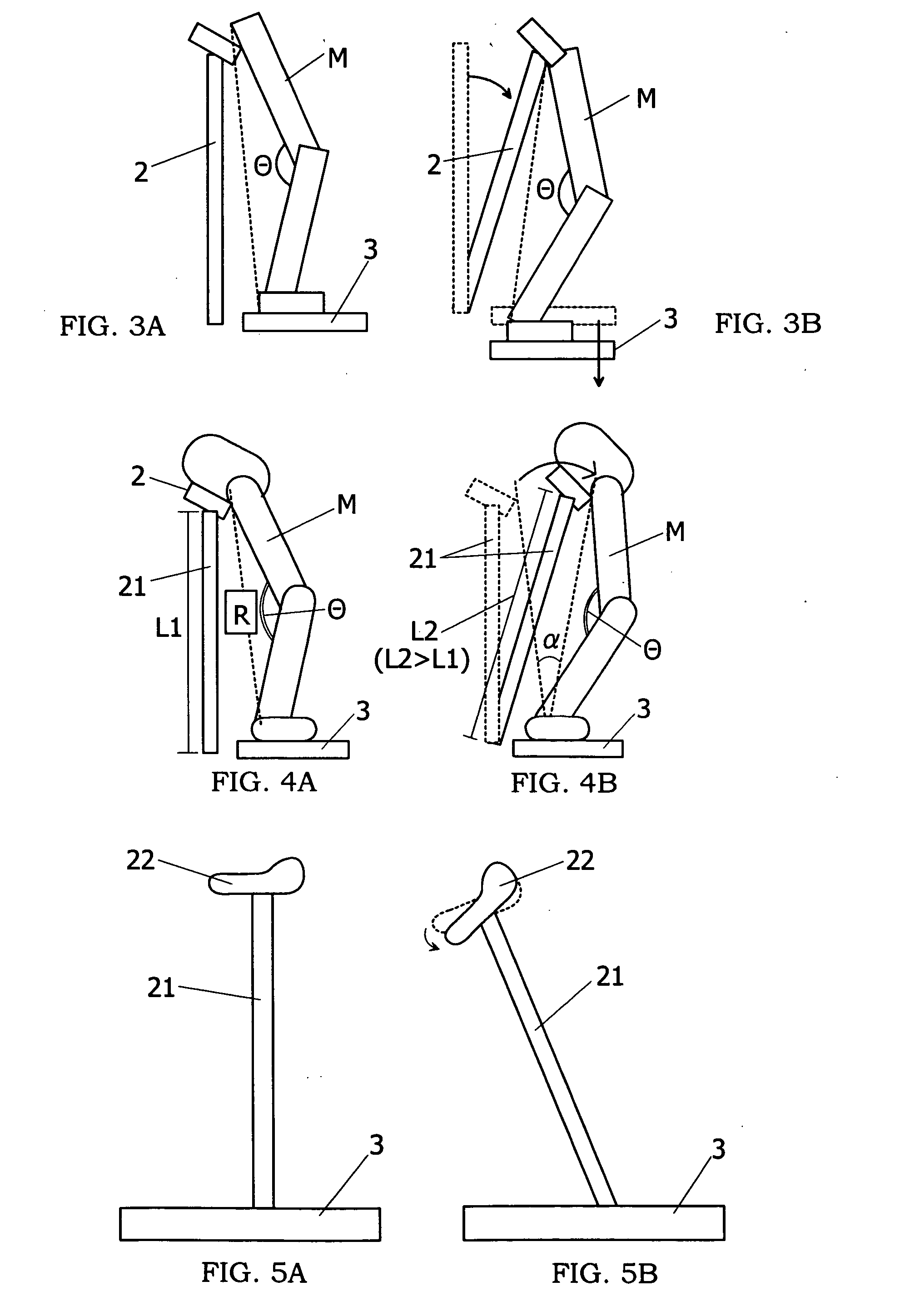
[0064] The seat member 2 is provided with a post 21, a saddle disposed at the top end of the post 21 to support the user's hip, and a joint portion 23 for joining the saddle with the post to provide parallel and rotational movements of the saddle relative to the post. The saddle is configured in such a triangular shape that its forward end portion (front side of the user sitting on the saddle 22) has a narrower width than the rearward end portion in a top plan view. The saddle 22 may be confi...

second embodiment

[0139] As shown in FIG. 21, this embodiment is directed to a leg training equipment for allowing the user to voluntarily perform a leg training without using any drive unit. That is, in the first embodiment, the motors 6 to 9 are used as the drive unit, so that the user passively receives the leg training without voluntarily performing exercises. In this embodiment, a seat member 2 and a footplate 3 are respectively coupled to a base 1 through coupling mechanisms 4, 5 without using the drive unit. The coupling mechanism 5 for coupling the footplate 3 to the base 1 provides an up and down movement of the footplate by use of a pantograph 51, as in the case of the first embodiment. As to the seat member 2, a post 21 is retractable to adjust the position of a saddle 22 in a height direction, and the saddle 22 connected to the post 21 can be inclined in a forward and backward direction about an (one) axis extending in a left and right direction. As in the case of the first embodiment, th...

third embodiment

[0144] In a leg training equipment 1 of this embodiment, a footplate 3 can be moved in only an up and down direction, and a distance between a bottom end portion of a seat member 2 and the footplate 3 is kept constant. That is, as shown in FIGS. 24A and 24B, by forming guide apertures 3a in four corners of a plate-like footplate 3, and inserting four guide pins 3b projecting on a base 1 into the guide apertures, the footplate can be moved in only the up and down direction. In this case, when a link body 70 is fixed to the seat member 2 and the footplate 3, the seat member can not be inclined against the base 1. Therefore, the link body 70 has hinges such as ball bearings at its opposite ends, which are engaged with the seat member 2 and the footplate 3, so that both of an angle between the seat member 2 and the link body 70 and an angle between the footplate 3 and the link body 70 become changeable. Thus, the footplate 3 can be moved in the up and down direction according to the osc...


PUM


Abstract

A leg training equipment has a base fixed in place, a support portion configured to support a part of a user's body, and a coupling mechanism provided between the base and the support portion. The coupling mechanism movably couples the support portion to the base such that a load applied to a leg of the user by the user's own weight changes by a relative positional displacement between a foot position and a position of center of gravity of the user. In addition, the coupling mechanism limits a movable direction of the support portion such that at least when the load applied to the leg increases, a direction of the relative positional displacement between the foot position and the position of center of gravity is substantially limited to a direction of flexion and extension of knee joint. Thereby, it is possible to efficiently provide the user with an exercise that applies less load on the knee joint.

Description

TECHNICAL FIELD [0001] The present invention relates to an equipment, which can be used by a user having knee pain to efficiently train leg muscles, and also preferable for the purpose of beauty exercises or overcoming physical laziness. BACKGROUND FIELD [0002] In the past, stationary cycling machines (indoor exercise bike) and stationary running machines (treadmill) have been well known as exercise assist devices for allowing a user to voluntarily train leg muscles. On the other hand, as another exercise assist devices for providing a passive exercise to the user without the user's voluntary action, horse-riding exercise machines (e.g., Japanese Patent Publication [kokai] No. 11-155836) have been proposed. [0003] When using the indoor exercise bike or the treadmill, there is a case that knee flexion and extension exercises are excessively provided, or a load larger than the user's own weight is applied to the knee joint. However, these are not appropriate for the user having knee p...

Claims


Application Information

Patent Timeline
Patent Type & Authority Applications(United States)
IPC IPC(8): A63B21/00A63B21/02A63B23/04
CPCA61H1/003A61H2201/5092A61H1/0255A61H2203/0406A61H2203/0425A61H2203/0481A63B21/00178A63B21/00181A63B21/068A63B22/16A63B22/18A63B23/0405A63B23/0494A63B24/00A63B69/0053A63B2208/0204A63B2208/0233A63B2208/0285A63B2220/13A63B2220/51A63B2225/093A63B2230/20A63B2230/60A61H2201/1215A61H2201/164A61H2201/5061A61H1/0229A63B23/08
Inventor OZAWA, TAKAHISASHINOMIYA, YOUICHIOCHI, KAZUHIROTOYOMI, YURITSUGUISHINO, KOUICHIKAWAMOTO, MINORU
Owner PANASONIC CORP
Why Eureka
Try Eureka