Adjustable splint for osteosynthesis

a splint and adjustable technology, applied in the field of adjustable splints for osteosynthesis, can solve the problems of limiting the options of practitioners, the orientation of bone screws is also limited, and the connection of the clamp to the longitudinal support is difficult to achiev

Active Publication Date: 2006-10-12
ORTHOPRO
View PDF99 Cites 99 Cited by
  • Summary
  • Abstract
  • Description
  • Claims
  • Application Information

AI Technical Summary

Benefits of technology

[0008] The adjustable splints of the present invention overcome the aforementioned disadvantages by providing a variety of different options for adjusting the locations and configurations of the splints. The adjustable mounts of the present invention can be moved to a variety of different locations with respect to the splint main body housings and the bone connectors can be rotated into a variety of positions within the mounts. Furthermore, the main bodies of the splint devices can be conveniently moved with respect to each other into a variety of different configurations and positions, thereby enabling them to be placed into a variety of different positions.

Problems solved by technology

One limitation to typical adjustable minisplint devices is that the clamp connected to the longitudinal support is only moveable in an axial, linear direction with respect to the longitudinal support.
The bone screws are also limited in their orientation.
This dynamic limits the practitioner's options when attempting to set one or more bones using such minisplint devices.
Another limitation with typical devices relates to the positioning of one longitudinal support with respect to another longitudinal support.
Such positioning typically results in limited movement, again reducing treatment options.
Yet another limitation associated with previous minisplint devices is that the lead screw used to provide adjustment of the bone clamps is retained in the longitudinal support body through the use of complicated multi-part systems that require a number of different parts to be added to the device assembly.
Another disadvantage of typical devices is that the lead screw of the devices projects outwardly from the elongated body, thereby exposing the lead screw to being inadvertently turned.

Method used


Image

  • Adjustable splint for osteosynthesis
  • Adjustable splint for osteosynthesis
  • Adjustable splint for osteosynthesis

Examples


Embodiment Construction

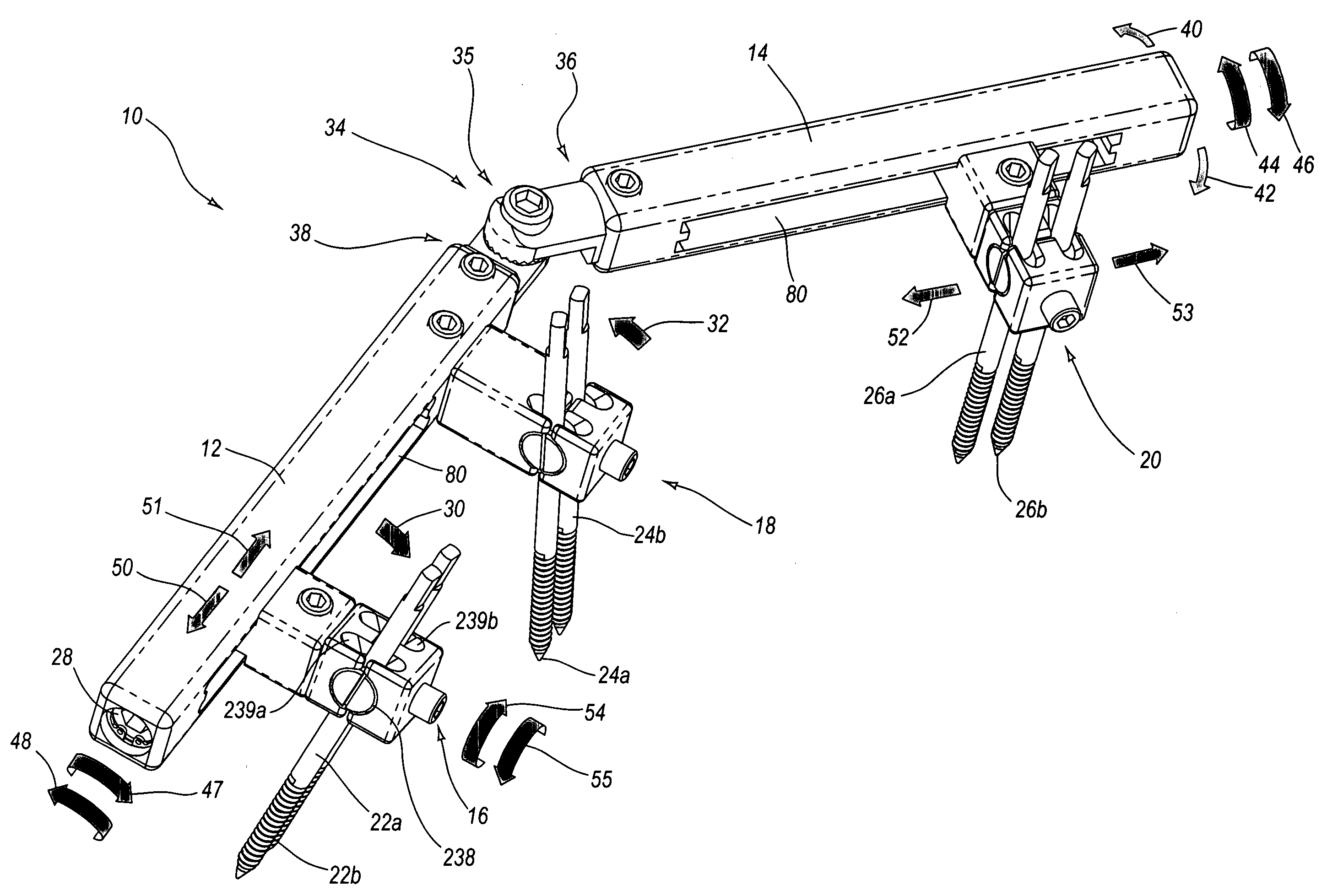
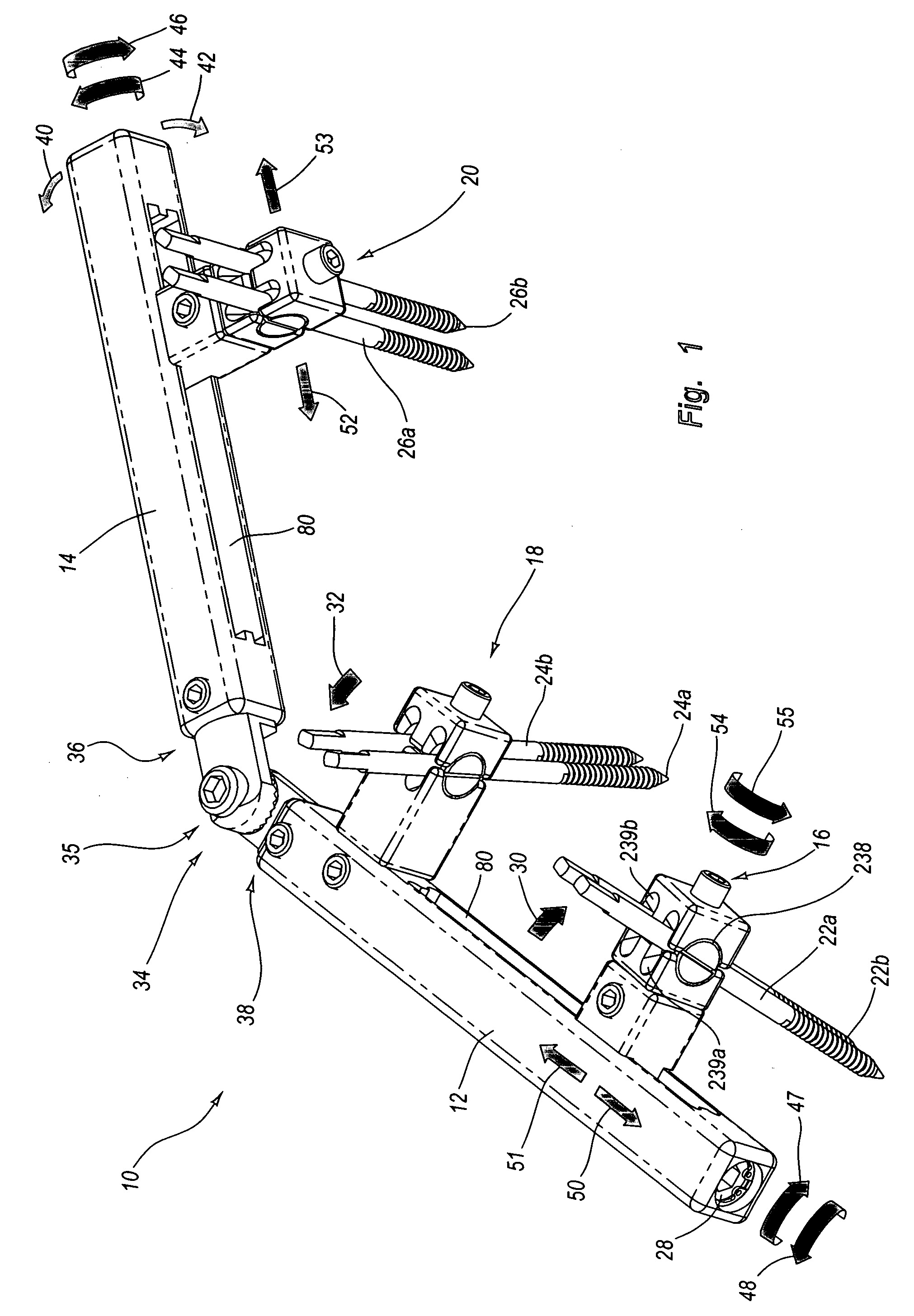
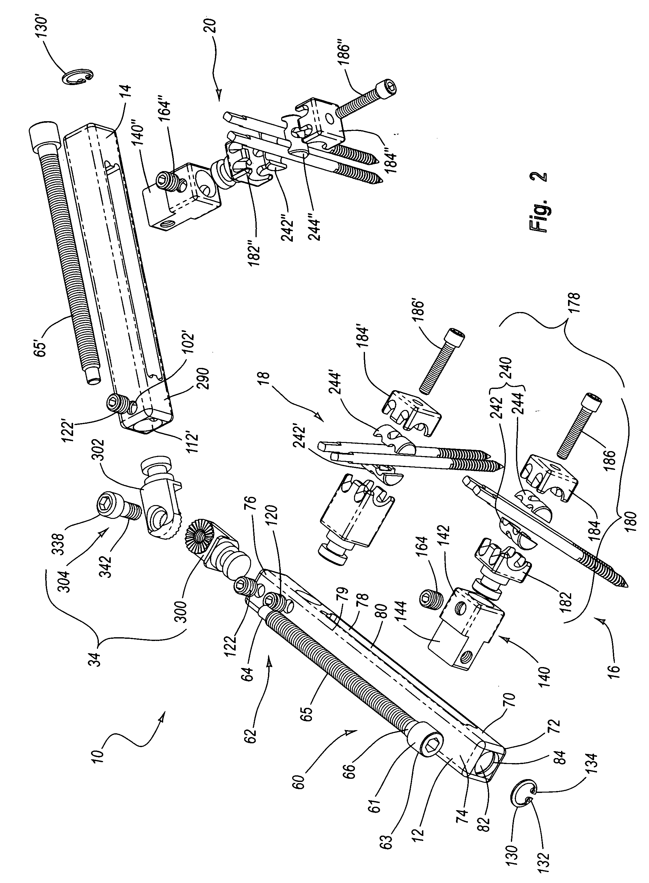
[0045]FIGS. 1-19 demonstrate examples of adjustable splints for osteosynthesis. FIG. 1 shows an adjustable splint 10 that is adjustable in more than one plane or axis, as illustrated by the arrows therein, thereby providing a variety of different, selectable splint configurations and treatment options for a practitioner. FIGS. 2-10 illustrate various individual components of splint 10, while FIGS. 11-14 illustrate various different positions in which the components of splint 10 can be moved to thereby provide adjustability and a variety of different optional configurations for the practitioner.

[0046] With reference now to FIG. 1, splint 10 has first and second main bodies 12, 14 to which respective first, second, and third mounts 16, 18, and 20 are coupled. Bone screws 22a-b, 24a-b, and 26a-b are coupled to respective mounts 16, 18, 20, and connect splint 10 to one or more selected bones during a bone splinting procedure. Each of these components may be selectively moved with respe...


PUM


Abstract

Adjustable splints for treating bone breaks and fractures provide a variety of different options for adjusting the locations and configurations of the splints. Adjustable mounts on the splints can be moved to a variety of different locations with respect to the splint main body housings and bone connectors can be rotated into a variety of positions within the mounts. Main bodies of the splint devices can be conveniently moved with respect to each other into a variety of different configurations and positions.

Description

FIELD OF THE INVENTION [0001] This patent application is in the field of adjustable splints for osteosynthesis. More specifically, this application relates to an adjustable splint device useful for treating the fracture of bones, e.g., ankle, wrist and facial bones. BACKGROUND OF THE INVENTION [0002] When fractured bones are properly splinted, they often are able to heal in an appropriate manner thereby simulating the shape and function of the previously uninjured, natural bone. Bone fixation devices are often employed in the treatment of fractures of small bones such as bones in the foot, hand or maxiofacial regions, but also with a variety of different bone types. Such fixation devices are often known as minisplint devices, particularly when used in treatment of the small bones. [0003] Typical minisplint devices feature a longitudinal support body and a pair of clamps mounted on the longitudinal support body. A clamp can be moved along the body through the use of an adjustable lea...

Claims


Application Information

Patent Timeline
Patent Type & Authority Applications(United States)
IPC IPC(8): A61B17/00
CPCA61B17/6416A61B17/66A61B17/6475A61B17/6425
Inventor OLSEN, RON ANTHON
Owner ORTHOPRO
Why Eureka
Try Eureka