Electro-hydraulic control process and work machine using same

a technology of electrohydraulic control and work machine, applied in process and machine control, program control, instruments, etc., can solve problems such as inability to master the operation of work machine for many hours, system speed or slowness, undesirable operating characteristics

Inactive Publication Date: 2006-10-12
CATERPILLAR INC
View PDF14 Cites 9 Cited by
  • Summary
  • Abstract
  • Description
  • Claims
  • Application Information

AI Technical Summary

Problems solved by technology

Skilled operators who attempt to operate many newer electro-hydraulic systems often find the systems to be too quick or too slow, or otherwise perceive them to have undesirable operating characteristics.
Mastery of work machine operation can take many hours, and it can therefore be costly and time consuming to require operators to learn the intricacies of work machine operation all over again when presented with a newer system.
Direct output based on a modulation map in such systems tends to be too fast and difficult to control in response to operator inputs.
As a result, many such systems are prone to operator-induced oscillations and overshoot or undershoot of the implement response the operator is attempting to control.
Moreover, each variety of movement, for example “lift” versus “tilt” may require its own degree of rate limiting.
The entire process typically results in extensive data sets.
Such approaches have met with some success, however, the tuning process tends to be quite time and labor intensive.
Engineers are therefore continually challenged to find ways of improving upon earlier control systems, and to develop easier means for preparing such systems for operation.

Method used


Image

  • Electro-hydraulic control process and work machine using same
  • Electro-hydraulic control process and work machine using same
  • Electro-hydraulic control process and work machine using same

Examples


Embodiment Construction

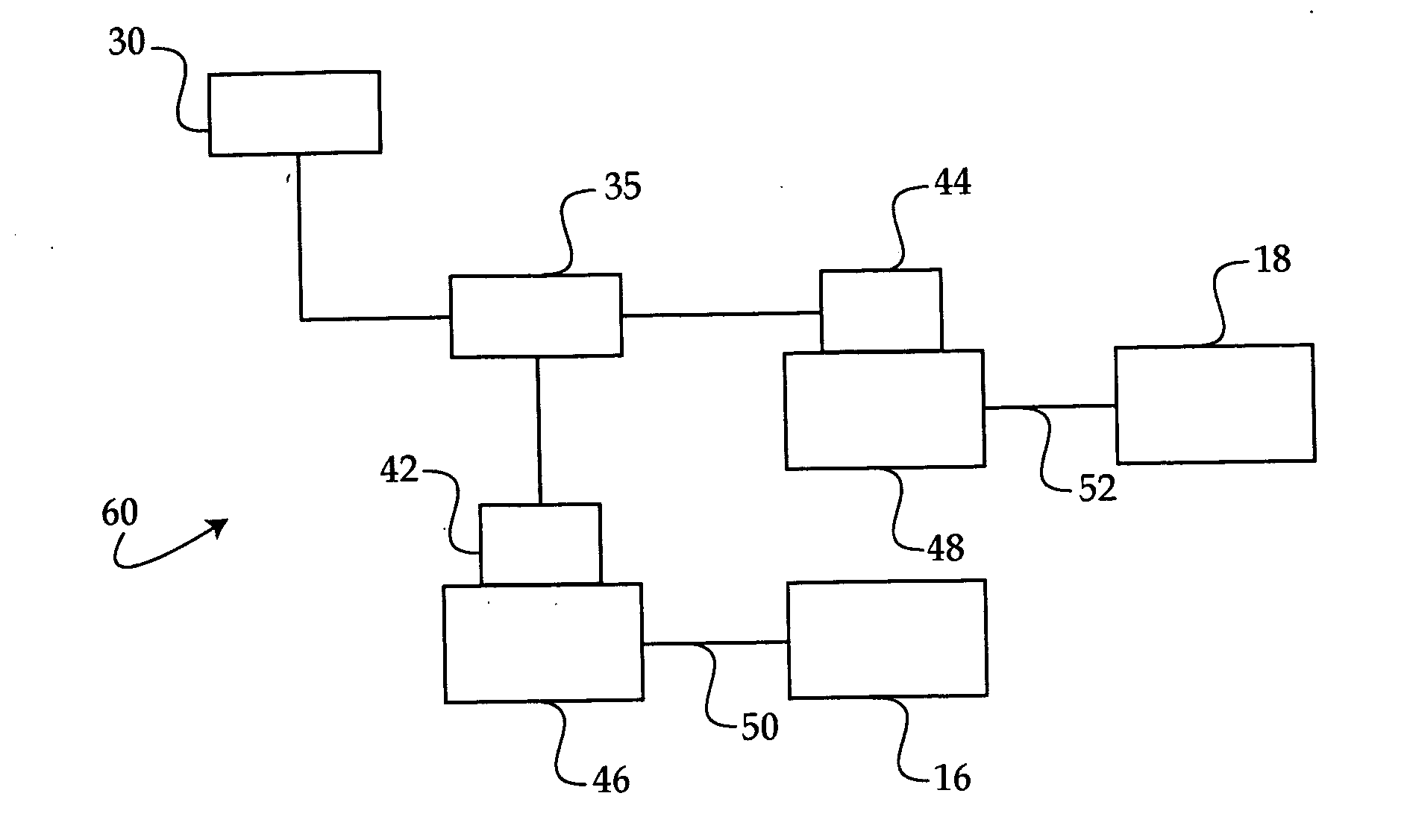
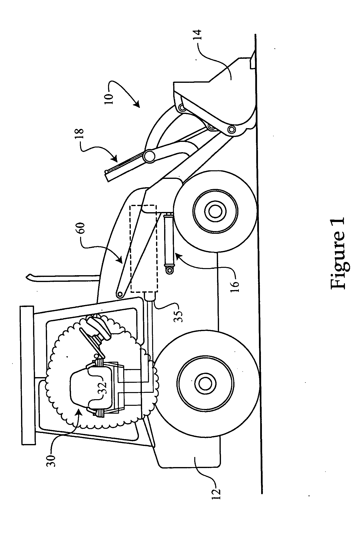
[0016] Referring to FIG. 1, there is shown a work machine 10 according to one embodiment of the present disclosure. Work machine 10 includes a work machine body 12 having a movable implement 14 such as a bucket coupled thereto. Work machine 10 may further include a manual operator input device 30, such as a pair of seat mounted control levers or joysticks 32. It should be appreciated that while dual control levers 32 are illustrated, alternatives are contemplated such as push buttons, a single control lever, or any other suitable means for inputting an operator's desired commands for work machine 10. Operator input device 30 will typically be operably coupled with an electronic control module 35. Electronic controller 35 is in turn part of an electro-hydraulic system 60, and may be in control communication with input device 30, as well as the other components of electro-hydraulic system 60, allowing an operator to request an adjustment thereto, as described herein. In one contemplat...


PUM


Abstract

A method of controlling an electro-hydraulic system is provided. The method includes receiving an input corresponding to an operator commanded adjustment of the system, and determining an output at a time increment to adjust the electro-hydraulic system based at least in part on the input, at least one output at a previous time increment and at least one predetermined damping constant. A work machine and method of preparing an electro-hydraulic system of a work machine for operation are also provided. The work machine includes an electro-hydraulic system with at least one movable control member, a manual input device and an electronic controller. The electronic controller includes a control algorithm for generating an output to adjust the position of the at least one movable control member. The method of preparing includes determining a damping constant for damping a response of the electro-hydraulic system, and programming an electronic controller of the work machine with a control algorithm for controlling the hydraulic system, and adjusting a position of the control member based at least in part on the at least one damping constant.

Description

TECHNICAL FIELD [0001] The present disclosure relates generally to electro-hydraulic control processes, and relates more particularly to a control process that artificially damps the response of a hydraulic system to an operator commanded adjustment. BACKGROUND [0002] Hydraulic systems are core components of many familiar work machines. For example, virtually all cranes, off-highway work machines, track-type and wheeled tractors and loaders include hydraulic systems for actuating their various implements. In a wheel loader, for example, the hydraulic system may be used to actuate hydraulic cylinders coupled with the bucket, for both raising / lowering and tilting. In a common traditional design, the wheel loader is equipped with manual controls inside an operator cab. A control lever, for example, allows an operator to control a flow of fluid into and out of one or more hydraulic cylinders, typically by adjusting the position of a pilot valve and thereby adjusting a fluid flow directi...

Claims


Application Information

Patent Timeline
Patent Type & Authority Applications(United States)
IPC IPC(8): G06F19/00
CPCG05B19/404G05B2219/42217G05B2219/39178
Inventor KURUP, PRASAAD B.HORTON, BRIAN D.
Owner CATERPILLAR INC
Why Eureka
Try Eureka