Weight compensating shock isolator assembly

a shock isolator and weight-compensating technology, applied in the direction of shock absorbers, chairs, machine supports, etc., can solve the problems of severe injury to seat occupants, inability to work well over a wide weight range of seat occupants, and system complexity in cost and manufacture, so as to effectively isolate seat occupants and wide weight range

Active Publication Date: 2014-08-05
ITT MFG ENTERPRISES LLC
View PDF15 Cites 3 Cited by
  • Summary
  • Abstract
  • Description
  • Claims
  • Application Information

AI Technical Summary

Benefits of technology

[0011]One advantage of the present invention is that adjustments of the herein described shock isolator assembly are not required, wherein the herein described system can effectively isolate seat occupants over a very wide weight range.
[0012]Another advantage is that the herein described shock isolator assembly is reusable and thus can be cycled many times, thereby isolating the seat occupant from the initial acceleration pulse from the blast and the second acceleration pulse from the “slam-down”, as well as multiple blast events.
[0013]Another advantage is that the shock isolator assembly controls the extension rate of the assembly to effectively isolate seat occupants during extension of the isolator such that the seat occupant does not become decoupled from the seat during extension of the isolator.
[0014]Yet still another advantage is that the herein described shock isolator assembly incorporates mechanical springs to provide the preload that is required to support the weight range. The mechanical springs provide a preload and spring rate that are not temperature sensitive so there is no variation in the spring load when used over a wide temperature range.

Problems solved by technology

Such blasts produce acceleration pulses that would be severely injurious to the seat occupant, including not only the initial blast but also the “slam-down” acceleration pulse that the occupant would be subjected to when the vehicle returns to the ground following the blast itself.
These devices are somewhat effective, but only work a single time and may not work well over a wide weight range of seat occupants.
These systems, however, are extremely complex in terms of their cost and manufacture.

Method used


Image

  • Weight compensating shock isolator assembly
  • Weight compensating shock isolator assembly
  • Weight compensating shock isolator assembly

Examples


Embodiment Construction

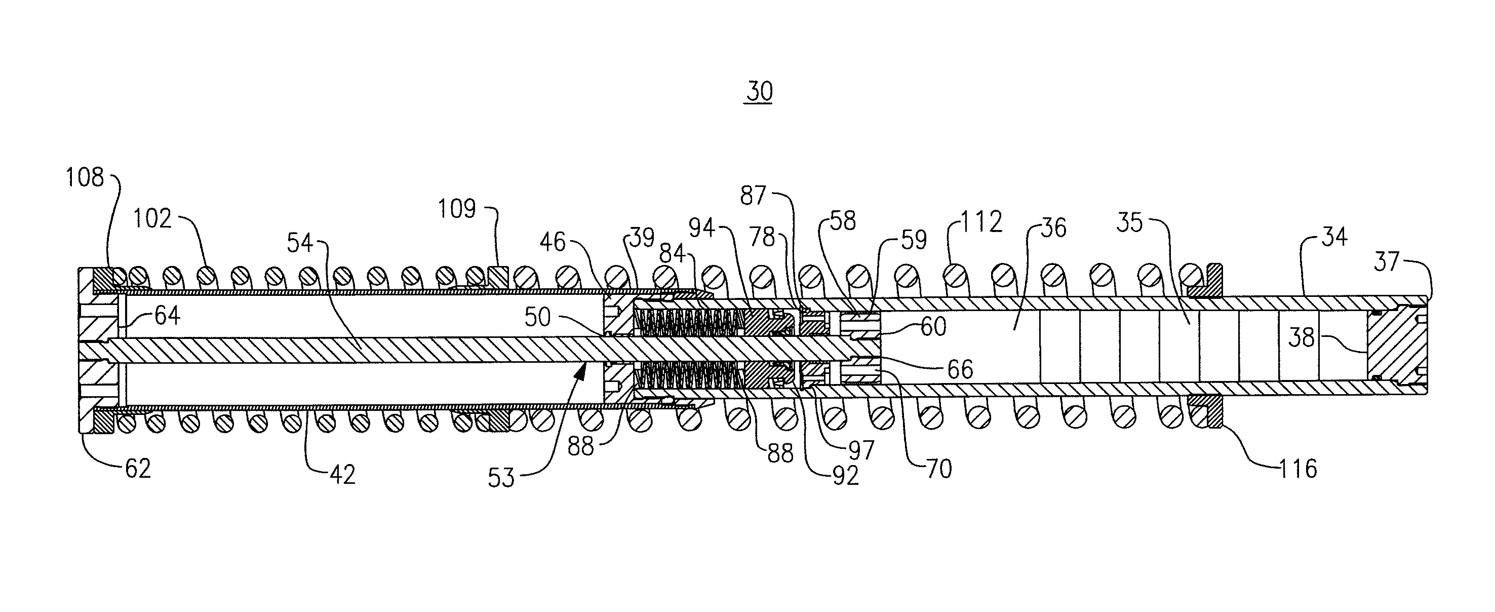
[0021]The following description relates to a weight compensating shock isolator assembly for use with at least one vehicle blast seat. Throughout the course of discussion several terms are used herein in order to provide a frame of reference with regard to the accompanying drawings, such as “distal”, “proximal”, “inner”, “outer”, “internal”, “external” and the like. It should be noted that these terms are not intended to be overly limiting with regard to the herein described invention, including the claims, except where so specifically indicated.

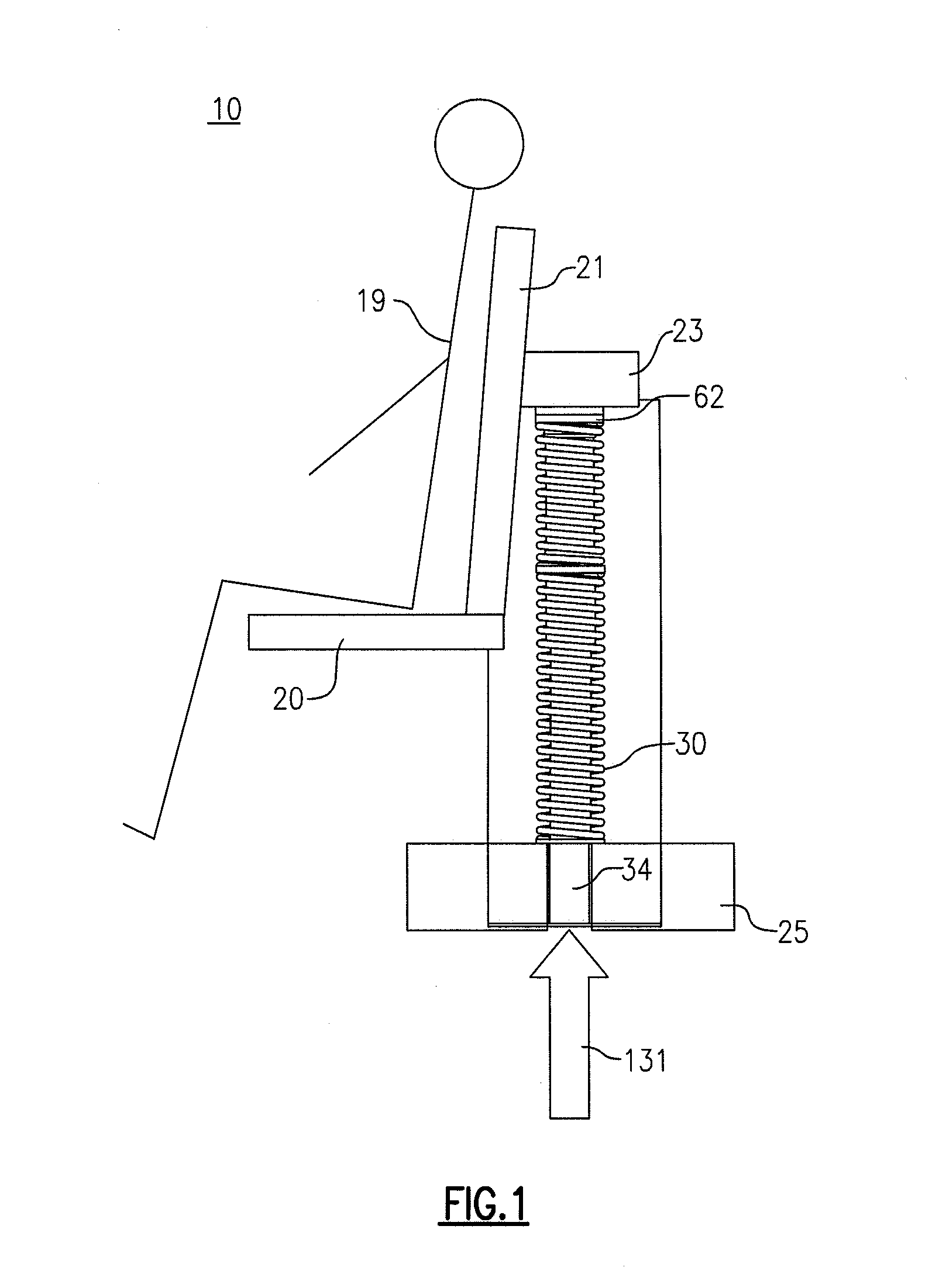
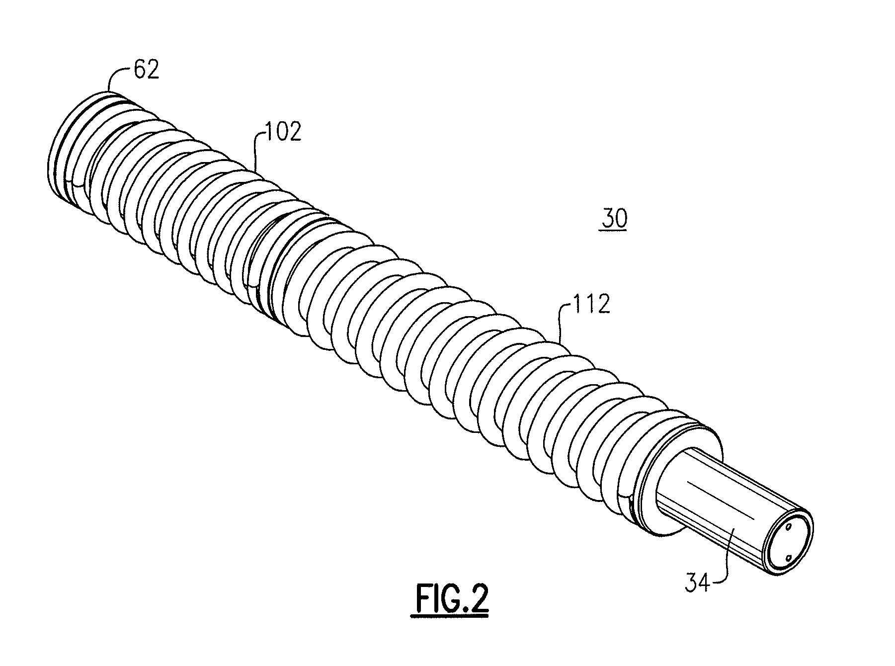
[0022]Referring to FIG. 1 there is schematically shown a shock isolator assembly 30, which is mounted to the rear of a vehicle blast seat 20. According to this embodiment, the shock isolator assembly 30 is vertically mounted in an orientation that is substantially parallel to the back rest 21 of the blast seat 20, wherein the blast seat is guided by means (not shown), such that the herein described isolator assembly receives only vertical lo...


PUM


Abstract

A weight compensating shock isolator assembly includes at least one spring with preload to return the isolator to an initial position, the at least one spring exerting a spring force that changes during the isolator stroke. The isolator includes a hydraulic cylinder containing hydraulic fluid and a piston that moves relative to the hydraulic cylinder, wherein hydraulic fluid is forced through or around a piston head during relative movement thereof with respect to the hydraulic cylinder to create a resisting force that is stroke and velocity dependent, with the damping constant C changing with stroke.

Description

FIELD OF THE INVENTION[0001]This application generally relates to the field of shock isolation devices and more specifically to a shock isolating assembly for isolating high acceleration loads to seats in a vehicle that could be subjected to a blast from under the vehicle. The herein described shock isolator assembly is self-resetting and therefore reusable, and also does not require a separate adjustment for use over a significant weight range of seat occupants wherein the assembly also effectively isolates over a wide temperature range.BACKGROUND OF THE INVENTION[0002]Military vehicles, such as personnel carriers and the like, include blast seats to protect the occupant from a blast occurring under the vehicle such as, for example, those caused by a landmine or improvised explosive device. Such blasts produce acceleration pulses that would be severely injurious to the seat occupant, including not only the initial blast but also the “slam-down” acceleration pulse that the occupant ...

Claims


Application Information

Patent Timeline
Patent Type & Authority Patents(United States)
IPC IPC(8): F16F9/49F16F7/00F16M1/00
CPCB60N2/503B60N2/24B60N2/4242B60N2/527B60N2/544F16F13/007
Inventor RUAN, SHUBINKELLY, JEFFREY T.
Owner ITT MFG ENTERPRISES LLC
Why Eureka
Try Eureka