Cyclone dust-collecting device and vacuum cleaner having the same

Inactive Publication Date: 2006-10-19
SAMSUNG GWANGJU ELECTRONICS CO LTD
View PDF4 Cites 196 Cited by
  • Summary
  • Abstract
  • Description
  • Claims
  • Application Information

AI Technical Summary

Benefits of technology

[0014] Accordingly, the air is prevented from being discharged towards a user or a cleaner surface. Therefore, dust on the cleaner surface are prevented from being scattered due to the air discharged from the vacuum cleaner and a cleaning efficiency can be maintained. Also, users do not feel unpleasant when using the vacuum cleaner. Also, the discharge c over prevents dirt from flowing into the cyclone du

Problems solved by technology

Due to the presence of the discharge passage, the conventional vacuum cleaner has a complicated structure, and thus, a manufacturing cost increases

Method used


Image

  • Cyclone dust-collecting device and vacuum cleaner having the same
  • Cyclone dust-collecting device and vacuum cleaner having the same
  • Cyclone dust-collecting device and vacuum cleaner having the same

Examples


Embodiment Construction

[0028] Hereinafter, the present invention will now be described in greater detail with reference to the accompanying drawings.

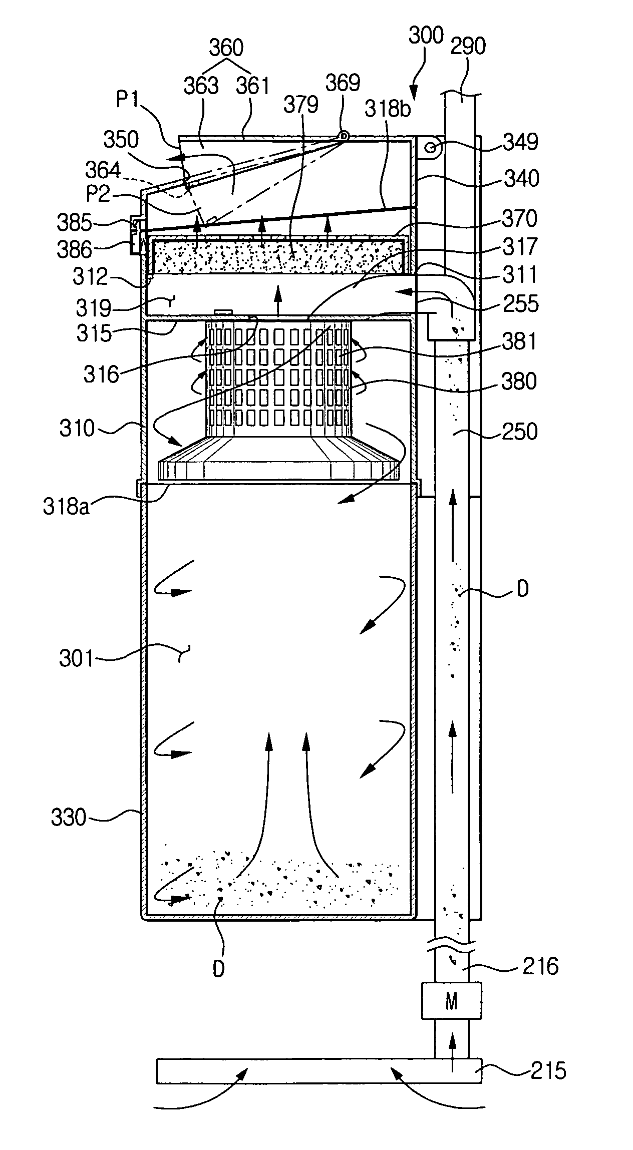
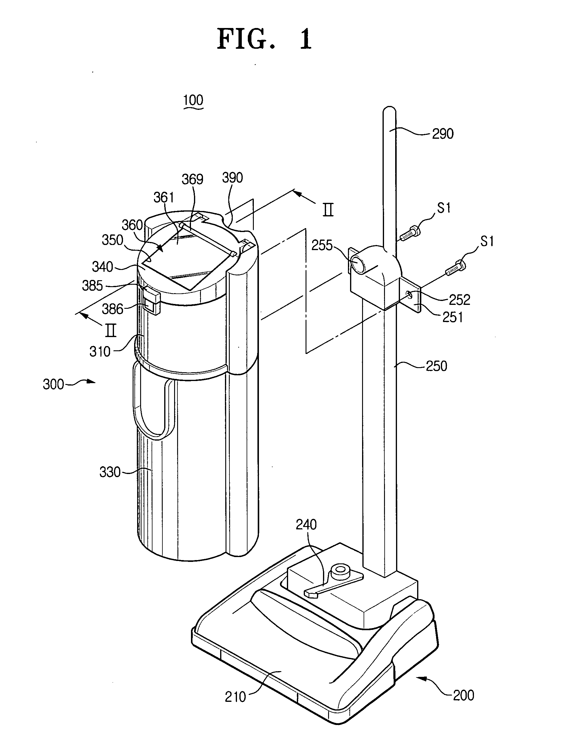
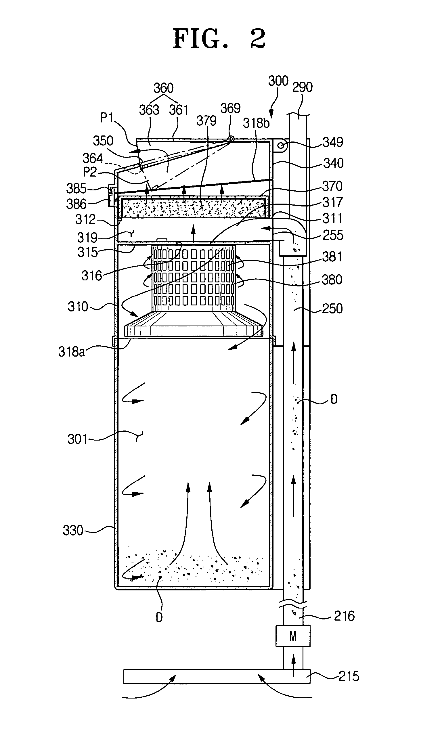
[0029]FIGS. 1 and 2 show one example of a vacuum cleaner according to an embodiment of the present invention. Referring to FIGS. 1 and 2, a vacuum cleaner 100 according to an embodiment of the present invention comprises a cleaner body 200 and a cyclone dust-collecting device 300.

[0030] The cleaner body 200 comprises a suction port assembly 210 having a dirt suction port 215 formed on a bottom thereof, a suction motor M generating a suction force at the dirt suction port 215, a suction pipe 250 and a handle 290. In this embodiment, the suction motor M is disposed at a channel 216 connecting the dirt suction port 215 and the suction pipe 250 and is a bypass motor. When the suction motor M is driven, dirt D (see FIG. 2) is drawn in from a cleaning surface through the dirt suction port 215 together with an ambient air, passes through the suction motor M and th...


PUM

PropertyMeasurementUnit
Circumferenceaaaaaaaaaa

Abstract

A vacuum cleaner includes a suction port assembly, a motor generating a suction force at the suction port assembly, and a cyclone dust collecting device for centrifugally separating air drawn in through the suction port assembly and the motor in sequence. The cyclone dust-collecting device includes an air discharge port penetratingly formed on an outer circumference of the cyclone dust-collecting device and exposed to an outside of the cleaner body, for guiding the air discharged to the outside. Accordingly, since the air discharge port is disposed in the cyclone dust collecting device, not in the cleaner body, a discharge channel for connecting the cyclone dust collecting device and cleaner body is omitted and thus a structure of the vacuum cleaner becomes simplified.

Description

CROSS-REFERENCE TO RELATED APPLICATIONS [0001] This application claims benefit under 35 U.S.C. §119 from Korean Patent Application No. 2005-32075, filed Apr. 18, 2005, the entire content of which is incorporated herein by reference. BACKGROUND OF THE INVENTION [0002] 1. Field of the Invention [0003] The present invention relates to vacuum cleaner, and more particularly, to a cyclone dust-collecting device for separating dirt from drawn-in air and a vacuum cleaner having the same. [0004] 2. Description of the Related Art [0005] A vacuum cleaner draws in dirt from a cleaning surface together with an ambient air and separates the dirt from the drawn-in air. A currently developed vacuum cleaner employs a cyclone dust-collecting device which separates dirt from drawn-in air using a centrifugal force. [0006] When the cyclone dust-collecting apparatus collects dirt as much as a predetermined amount, a user dismounts a dirt receptacle from the vacuum cleaner, empties the dirt receptacle and...

Claims


Application Information

Patent Timeline
IPC IPC(8): B01D50/00
CPCA47L9/1658A47L9/1691B01D45/14B01D2279/55B01D46/10B01D50/002B01D46/0004Y10S55/03B01D50/20A47L5/28B04C5/185B04C5/187H01Q9/0421H01Q1/243H01Q9/42H01Q1/38
Inventor OH, JANG-KEUNSEO, JI-WON
Owner SAMSUNG GWANGJU ELECTRONICS CO LTD
Why Eureka
Try Eureka