
Sensor devices

a sensor and sensor technology, applied in the direction of mechanical vibration separation, volume/mass flow by dynamic fluid flow effect, liquid/fluent solid measurement, etc., can solve the problem of limiting the useable measurement range of the flow meter, unable to obtain a construction resistant to vibration, temperature shock and corrosive media, and sensor only having limited temperature resistan

Active Publication Date: 2006-10-19
SHRIKRISHNA VAIDYA AVINASH
View PDF6 Cites 51 Cited by
  • Summary
  • Abstract
  • Description
  • Claims
  • Application Information

AI Technical Summary

Benefits of technology

[0018] An object of this invention is to provide a sensor device for flow meters and like instrument which is able to sense the desired signal and in the arrangement of which extraneous noise signals are prevented in a single sensing element itself without the need for providing additional sensing elements or using complicated means for separation of noise signals from the output signals.
[0020] Still another object of the invention, is to provide a robust sensor device which can be used for detection and measuring a wide variety of varying force pulse signals, such force being generated by pressure, vibration stress or strain.

Problems solved by technology

The prior art sensor devices typically in instruments such as flow meters have the problem that it has proved impossible to obtain a construction resistant to vibration, temperature, temperature shock and corrosive media.
If piezoelectric sensors are disposed inside the instruments, they are mechanically so connected thereto the sensor has only limited resistance to temperature and shock.
Such deflective sensors have the disadvantage that they are unable to discriminate between external vibrations in addition to frequency and amplitude of the signals generated for instance, by the flow of fluid External vibrations degrade the output signal from the sensor, and restrict the lower end of the useable measurement range of the flow meter.
A solid construction can not be attained due to flexibility of the sensor and the diaphragm.
Moreover, because of oil, the sensor device could not be operated in a high temperature range.
However, the sensor device does not at all tackle ambient noise signals.
However, disadvantageously, this type of vortex flow meter is adversely affected or influenced, for example, by disturbance vibration, such as piping vibration caused by operation of a pump.
Not only is this design of a sensor device very complicated it requires precise deduction of the spots at which the sensors are to be placed.
Since noise signals may emanate from unexpected sources such an arrangement becomes not only expensive but impractical in actually eliminating noise signals.
This approach is expensive, complex, and again has only had limited success.
While this approach has been more successful, the configuration of these instruments have certain inherent disadvantages including that of being very expensive and delicate.
However, the vanes transmit noise signal along with the required signal and hence this is the main cause of the signal to noise ratio being poor.
Also, the K factor cannot remain constant over the entire range of flow rates.
Following this approach inevitably, lower frequency signals go unattended reducing the sensitivity of the instrument and that of the measuring technique as a whole.

Method used


Image

  • Sensor devices
  • Sensor devices
  • Sensor devices

Examples


Embodiment Construction

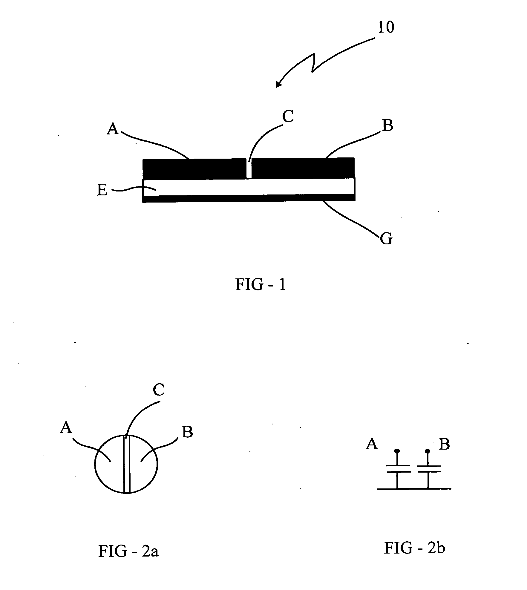
[0079] Referring to the drawings, FIGS. 1 and 2 shows schematically a piezoelectric element used for sensing devices in the prior art.

[0080] The sensing element shown in FIG. 1 consists of typically two semicircular halves A and B of a Piezo electric disc generally indicated by the reference numeral 10 divided by a plane including the non sensing space C and provided on a ceramic substrate E with the reference electrode G on the bottom surface of the substrate E. The electrodes A and B are alternatively compressed by oscillatory impulses acting on them. The two semicircular halves of the Piezo electric disc 10 with reference to the reference electrode are represented by the electric circuit representation in FIG. 2b.

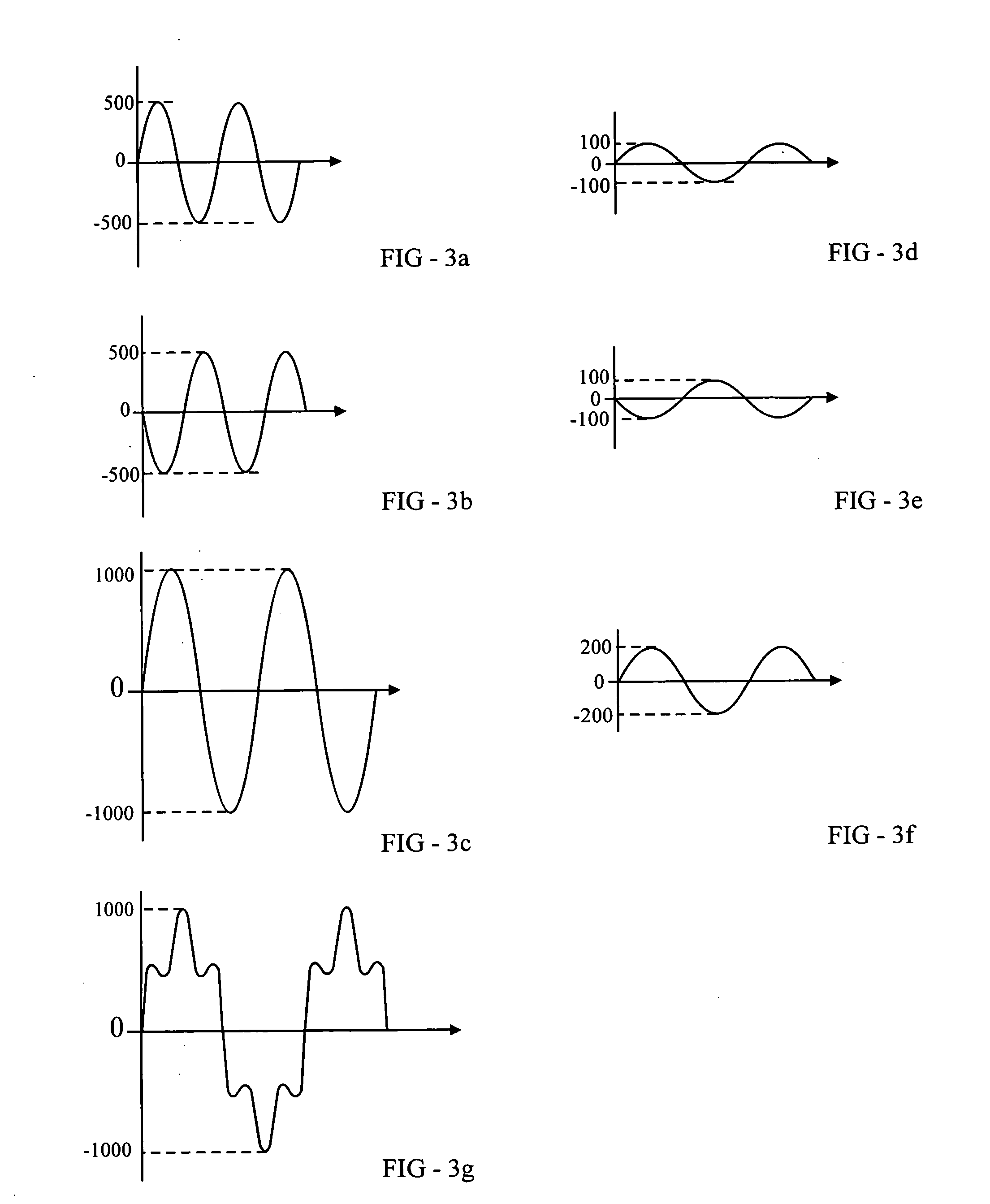
[0081] The output signals in response to a measurand are graphically represented in FIG. 3(a), 3(b) and 3(c) in which FIG. 3(a) represents the output signals of electrode A to a measurand, 3(b) represents the output signals of electrode B to the measurand, and 3(b) rep...


PUM


Abstract

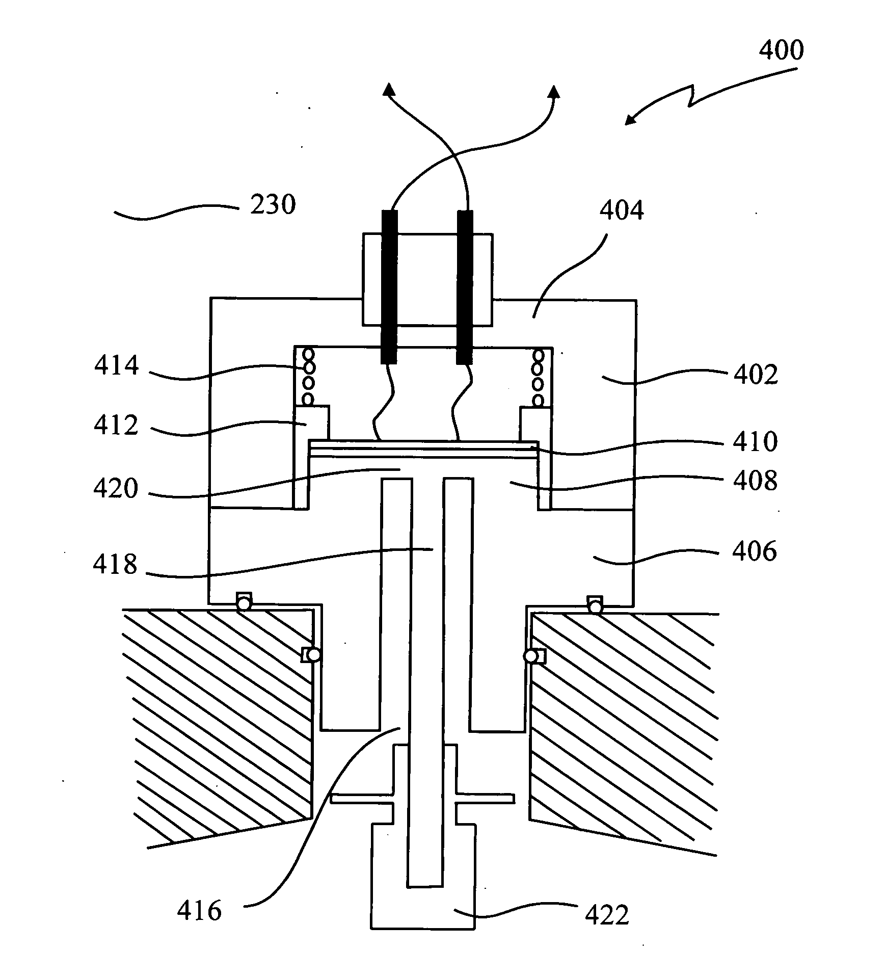
A sensor device for measuring frequency and amplitude of a varying force signal is provided. The sensor device comprises a sensing element defined by a plurality of even numbered planar segments symmetrically disposed about a central axis, a protective housing for housing, an interface element comprising a pick up member, a planar mechanical actuator, a transfer member adapted to receive varying signals from the pick up, amplify the signals picked up and transfer the amplified signals to the said mechanical actuator; and leads for transmitting said output signals outside the sensing device for processing.

Description

FIELD OF THE INVENTION [0001] This invention relates to sensor devices. [0002] In particular, this invention relates to sensor devices for measuring frequency and amplitude of varying force signals. BACKGROUND OF THE INVENTION [0003] The prior art sensor devices typically in instruments such as flow meters have the problem that it has proved impossible to obtain a construction resistant to vibration, temperature, temperature shock and corrosive media. Use is made of strain gauges disposed on the outside of the plate. If piezoelectric sensors are disposed inside the instruments, they are mechanically so connected thereto the sensor has only limited resistance to temperature and shock. [0004] The prior art sensor devices typically include a probe or signal pick up means usually fitted in juxtaposition with a signal generator such as a bluff body of a vortex flow meter, either within it or aligned down stream to it and the sensing element is usually located outside the fluid conduit an...

Claims


Application Information

Patent Timeline
IPC IPC(8): G01F1/32
CPCG01F1/3263B06B1/0622G01F1/3266
Inventor SHRIKRISHNA, VAIDYA AVINASH
Owner SHRIKRISHNA VAIDYA AVINASH
Learn More