Magnetic head testing apparatus

a testing apparatus and magnetic head technology, applied in hydrodynamic testing, functional testing of recording heads, instruments, etc., can solve the problems of difficult to observe how well the magnetic head has performed a writing, difficult to observe the overlap of a plurality of waveforms, and the amount of time required for investigative testing, etc., to achieve the effect of improving the accuracy of phase matching of a plurality of measured data

Inactive Publication Date: 2006-08-01
FUJITSU LTD
View PDF2 Cites 0 Cited by
  • Summary
  • Abstract
  • Description
  • Claims
  • Application Information

AI Technical Summary

Benefits of technology

[0008]The present invention therefore enables acquisition of the MR head characteristics and easier data analysis by comparing many signal waveforms through an overlap-display thereof, but avoiding noise signals, which can change when observed.
[0009]Furthermore, the present invention improves accuracy of overlap through amplitude compensation and phase compensation when the waveforms are overlapped, and thereby calculates a Viterbi Metric Margin (VMM) value to analyze the MR head in detail.
[0011]According to this structure, the measured data of the reproduced data (which consists of preamble, measured data, and postamble, etc.) that is read out a plurality of times may change due to fluctuation of a disk rotation, but is matched with the reference sampling number based on the same calculated ratio in comparison with the reference sampling number. As a result, since the measured data, which is measured of a plurality of times, can be overlapped in a same reference. Therefore, the characteristic of the MR head can be more easily confirmed.
[0013]Since frequency fluctuations in the preamble and postamble can be approximated to an average value of each phase difference according to this preferred structure, accuracy of the phase matching of a plurality of measured data can be improved.
[0015]According to this preferred structure, variation of period in the preamble and postamble can be approximated to an average value of phase differences, and the amplitude can be set to an optimum value. Accordingly, accuracy of phase matching of a plurality of measured data can also be improved. Moreover, the MR head can be analyzed in greater detail by calculating the VMM value.

Problems solved by technology

Known magnetic head testing apparatuses, however, experience problems with the amount of time required for investigative testing.
Moreover, since the waveform read-out includes electronic noise, which can randomly change during any reading, and a medium noise, which can randomly change during any writing, it is difficult to observe how well the magnetic head has performed a writing.
Additionally, the waveforms often lose their phase characteristics, and therefore it has also been impossible to observe overlap of a plurality of waveforms.

Method used


Image

  • Magnetic head testing apparatus
  • Magnetic head testing apparatus
  • Magnetic head testing apparatus

Examples


Embodiment Construction

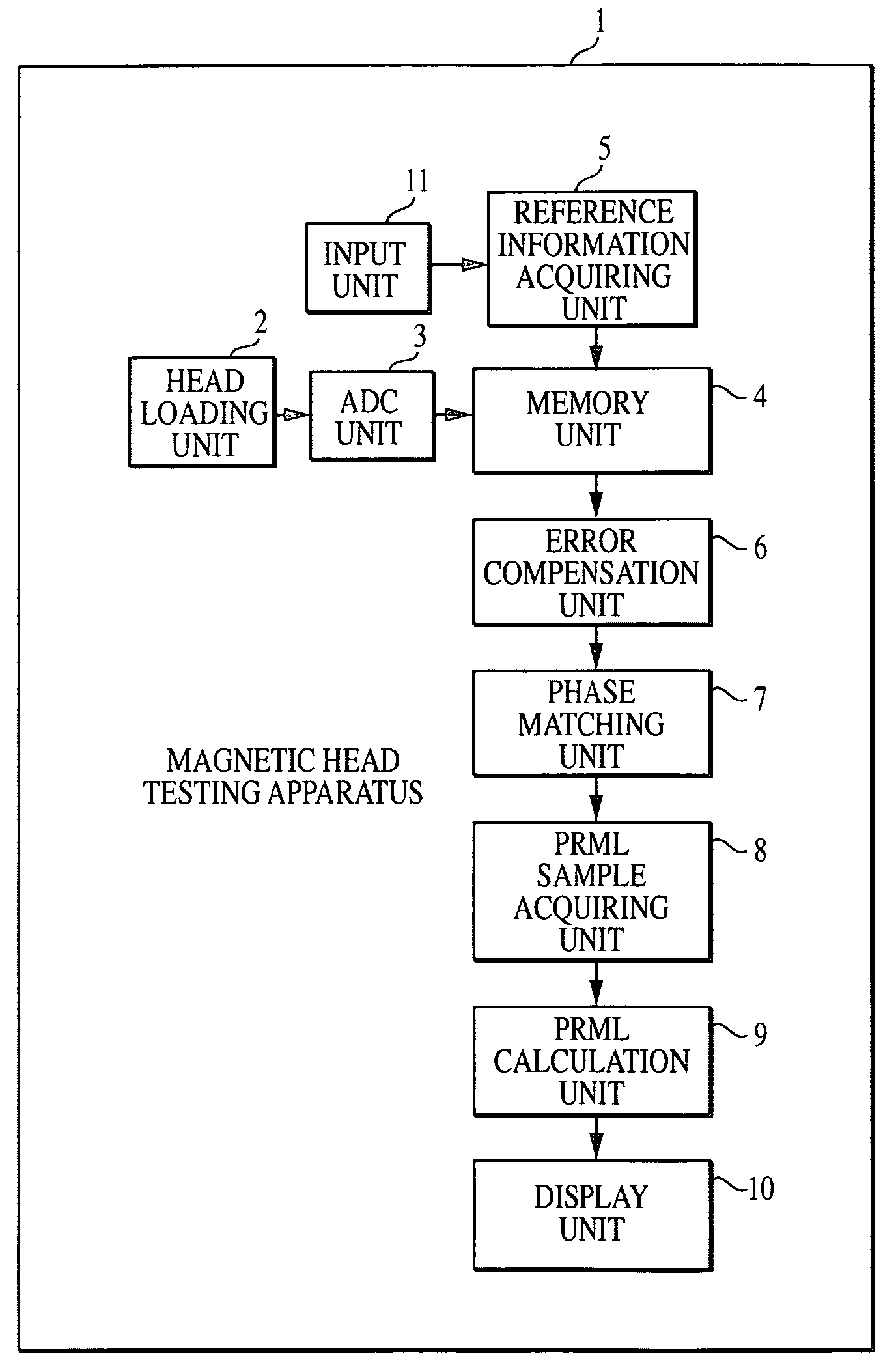
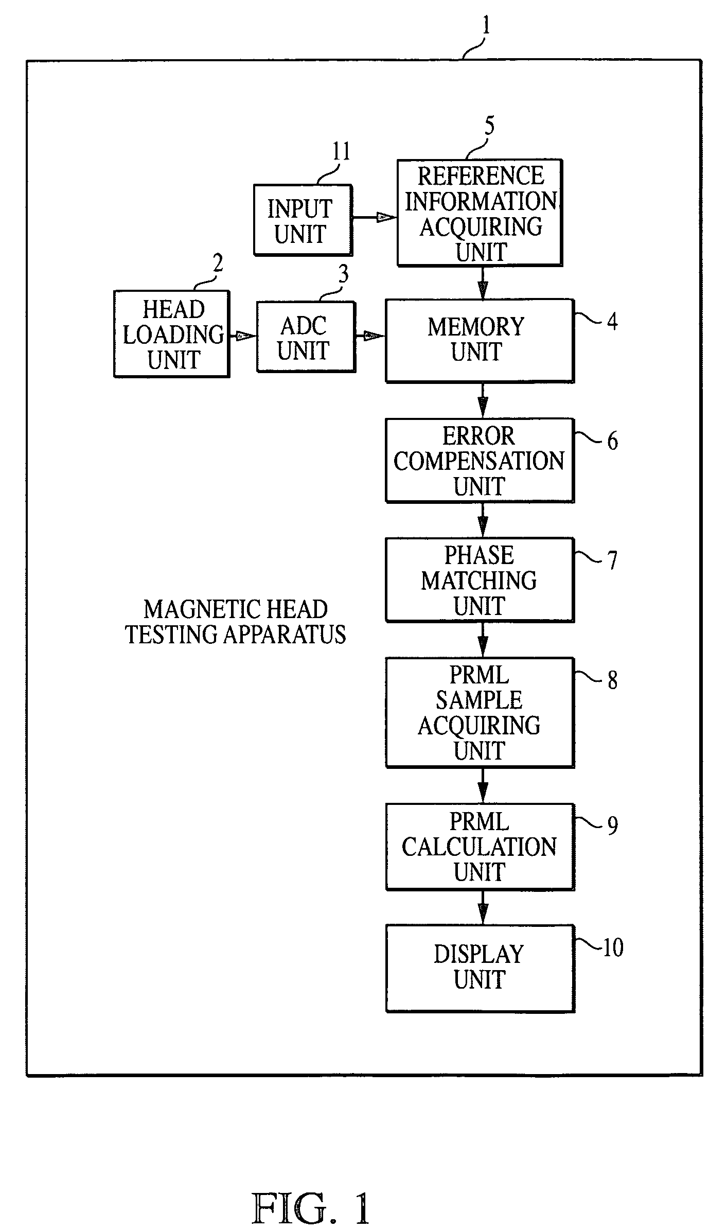
[0026]FIG. 1 illustrates a structure of a magnetic head testing apparatus according to a first embodiment of the present invention. A magnetic head testing apparatus 1 includes a head loading unit 2 for loading an MR head (not numbered) for testing, an analog-digital converter (ADC) unit 3 for converting an analog signal to digital data, a memory unit 4 for storing the converted digital data, a reference information acquiring unit 5 for acquiring a reference sample period and reference sampling number, an error compensating unit 6 for phase compensation of fluctuation error of measured data, a phase matching unit 7 for matching the measured data to a phase of the reference waveform data, a PRML sample acquiring unit 8 for acquiring a PRML sample, a PRML calculating unit 9 for calculating the PRML sample, a display unit 10 for overlap-display of data based on sampling data or the like, and an input unit 11 for inputting reference information.

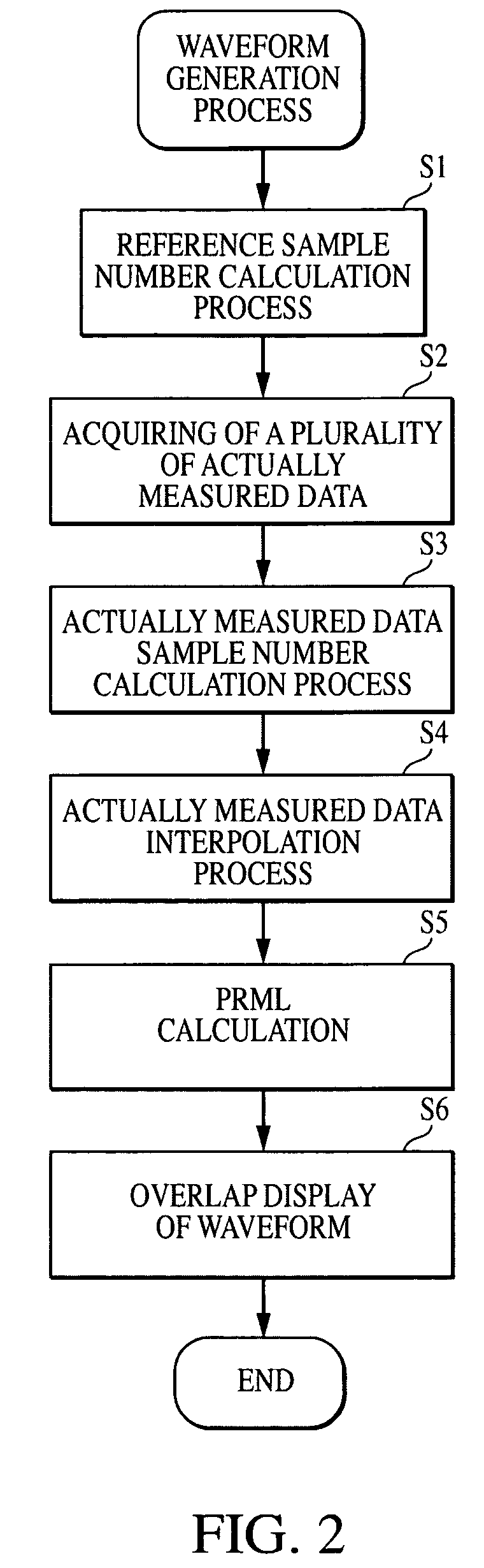
[0027]Referring now to FIGS. 2 and 3, a da...


PUM

PropertyMeasurementUnit
frequencyaaaaaaaaaa
magnetic head testingaaaaaaaaaa
magnetic head testing apparatusaaaaaaaaaa

Abstract

A magnetic head testing apparatus includes reference information storing unit for holding a predetermined reference sampling period and a number of reference samplings, sampling unit for sampling reproduced data read a plurality of times from a magnetic medium in the reference sampling period, sampling number acquiring unit for acquiring a sampling number of measured data from a reproduced data base on a sampling result, sampling number ratio calculating unit for calculating a ratio of the sampling number of the measured data and the number of reference samplings, sampling data re-acquiring unit for changing the sampling period of the measured data depending on the calculated ratio and re-acquiring the sampling data and a measured data overlap-displaying unit for overlap-display of the sampling data re-acquired from the measured data a plurality of times.

Description

[0001]This is a Continuation of Provisional Patent Application No. 60 / 415,031, filed Oct. 1, 2002.BACKGROUND OF THE INVENTION[0002]1. Field of the Invention[0003]The present invention relates to magnetic head inspecting apparatuses, and more particularly to magnetic head apparatuses for testing a magnetic head loaded to a magnetic disk apparatus.[0004]2. Description of the Related Art[0005]In recent years, further improvements in recording density, high speed transfer of data, and high-speed rotation of spindles have been required for magnetic disk apparatuses. To attain such requirements, a Magnetic Resistive (MR) head has been used which can obtain a reproduced signal of high output level, without relation to the number of rotations (circumference speed) of a disk medium. A signal recording system for such magnetic disk apparatuses has been mainly based on the Partial Response Maximum Likelihood (PRML) technique, however, a fluctuation of signal levels has been shown to increase c...

Claims


Application Information

Patent Timeline
Patent Type & Authority Patents(United States)
IPC IPC(8): G01R35/00G11B5/00G11B5/09G11B5/455
CPCG11B5/455G11B5/09G11B2005/0016G11B2005/0013
Inventor ARATANI, TAKETOSHIMUKUNOKI, TETSUYAHASHIZUME, KAZUTERUSUGAWARA, TAKAOYAGYU, KIYOHARU
Owner FUJITSU LTD
Why Eureka
Try Eureka