
touch screen, touch LCD

A liquid crystal display and touch screen technology, applied in instruments, computing, electrical and digital data processing, etc., can solve the problems of affecting accuracy, reducing the driving electrode area, occupying the touch screen area, etc., to increase the coupling capacitance, avoid noise signals, The effect of improving accuracy

Active Publication Date: 2016-03-16
SHANGHAI TIANMA MICRO ELECTRONICS CO LTD
View PDF6 Cites 0 Cited by
  • Summary
  • Abstract
  • Description
  • Claims
  • Application Information

AI Technical Summary

Problems solved by technology

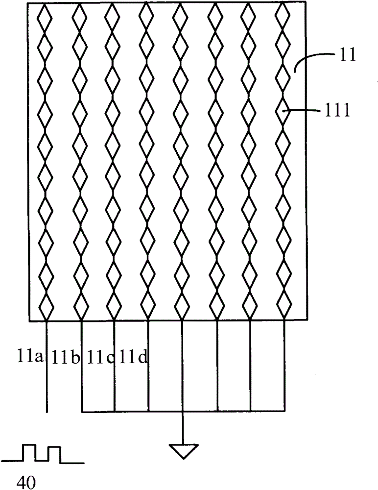
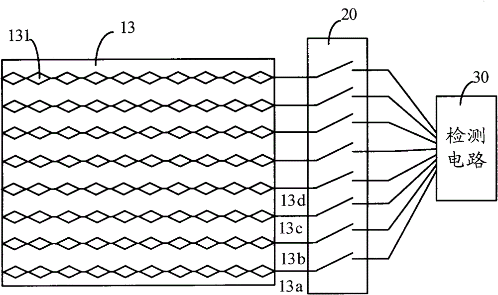
When a finger touches the touch screen, for example Figure 5 In the position indicated by the middle circle, the finger forms a coupling capacitance with the driving electrode 71d, and also forms a coupling capacitance with the connection lines 16a, 16b, 16c, and 16d, and the coupling capacitance formed between the finger and the connection lines 16a, 16b, 16c, and 16d also forms a coupling capacitance. It will change the mutual capacitance, so that noise signals will be mixed into the signal detected by the detection circuit, which will affect the accuracy of detection
[0013] In addition, since the connecting wires 16a, 16b, 16c, 16d, and 16e are arranged in parallel in the single-layer touch screen, the area of ​​the touch screen will be occupied, so that the area of ​​the driving electrodes located below becomes smaller.
like Figure 5 As shown, the area of ​​the driving electrodes 71e in the last row is much smaller than the area of ​​the driving electrodes 71a in the first row, and the smaller the area of ​​the driving electrodes, the smaller the coupling capacitance between the driving electrodes and the finger, thereby increasing the detection circuit's interaction with each other. The difficulty of detecting capacitance changes will also affect the accuracy of detection

Method used


Image

  • touch screen, touch LCD
  • touch screen, touch LCD
  • touch screen, touch LCD

Examples


Embodiment Construction

[0039] In order to make the above objects, features and advantages of the present invention more comprehensible, specific implementations of the present invention will be described in detail below in conjunction with the accompanying drawings.

[0040] In the prior art, a plurality of connection lines of the touch screen are arranged in parallel in the touch screen, which will occupy a certain area, so that when a finger touches the touch screen, the connection lines will be touched, and coupling capacitance will be generated, so that the signal detected by the detection circuit will be mixed with This will affect the accuracy of detection; at the same time, the multiple connecting lines arranged in parallel in the touch screen will also reduce the area of ​​the driving electrode, which will reduce the coupling capacitance between the driving electrode and the finger, which will affect the detection. accuracy.

[0041] In view of the above problems, the present invention provi...


PUM


Abstract

A touch screen and a touch liquid crystal display comprising the same are disclosed. The touch screen comprises an electrode layer, a connecting wire layer, and an insulating medium layer located between the electrode layer and the connecting wire layer, wherein the electrode layer comprises a drive electrode and a sensing electrode; the driver electrode and the sensing electrode are used for mutual capacitance; the connecting wire layer comprises a connecting wire for realizing electric connection of the drive electrode with a drive wire with the peripheral region of the touch screen; and the insulating medium layer comprises a via hole for realizing the electric connection of the drive electrode with the connecting wire. The touch screen is high in the accuracy of detecting a finger touch position.

Description

technical field [0001] The invention relates to the field of touch displays, in particular to a mutual capacitance touch screen. Background technique [0002] As an input medium, the touch screen is currently the simplest, most convenient and natural way of human-computer interaction. Therefore, touch screens are more and more applied to various electronic products, such as mobile phones, notebook computers, MP3 / MP4, and the like. In order to reduce the cost of various electronic equipment and make various electronic equipment lighter and thinner, usually a touch screen is integrated into a liquid crystal display panel. [0003] Depending on the working principle and the medium used to detect touch information, touch screens can be divided into four types: resistive, capacitive, infrared, and surface acoustic wave. Capacitive touch screen technology has become the current mainstream touch screen technology due to its simple process, long life, and high light transmittance....

Claims


Application Information

Patent Timeline
Patent Type & Authority Patents(China)
IPC IPC(8): G06F3/044
Inventor 陈悦丁小梁王丽花臧浩春马从华
Owner SHANGHAI TIANMA MICRO ELECTRONICS CO LTD
Learn More