Fluid-magnetizing device

a fluid magnetizing and fluid technology, applied in the direction of moving filter element filters, filtration separation, separation processes, etc., can solve the problems of weaker magnetism, limited magnetizing effect, thin magnetic lines, etc., to prolong the contact time between fluid and magnetic lines, efficient magnetizing fluid, and prolong the magnetic lines

Inactive Publication Date: 2006-10-19
CHANG JEN PEN
View PDF6 Cites 3 Cited by
  • Summary
  • Abstract
  • Description
  • Claims
  • Application Information

AI Technical Summary

Benefits of technology

[0004] It is therefore a primary object of the present invention to provide an improved fluid-magnetizing device including an arced magnetic collar and multiple magnetic elements disposed on the magnetic collar. The magnetic collar is located around a fluid pipeline. At least one spiral flow guiding plate is disposed inside the fluid pipeline for guiding the fluid to spirally flow through the fluid pipeline. Accordingly, the contact time between the fluid and the magnetic lines is prolonged. In addition, the multiple magnetic elements are separately arranged to enhance and extend the magnetic lines so as to more efficiently magnetize the fluid in the fluid pipeline.

Problems solved by technology

In addition, the farther the magnetic lines are away from the magnetic poles, the thinner the magnetic lines are (the weaker the magnetism is).
Therefore, in the case that the magnetic bodies are simply disposed on two sides of a fluid passage, the magnetizing effect is limited.
Therefore, in the case that the circular magnets are respectively arranged on two sides of the water passage, the magnetic lines of the magnets are not fully utilized to achieve highest magnetization efficiency.
Therefore, the manufacturing cost for such device is relatively high.
This fails to meet the requirement of economy.

Method used


Image

  • Fluid-magnetizing device
  • Fluid-magnetizing device
  • Fluid-magnetizing device

Examples


Embodiment Construction

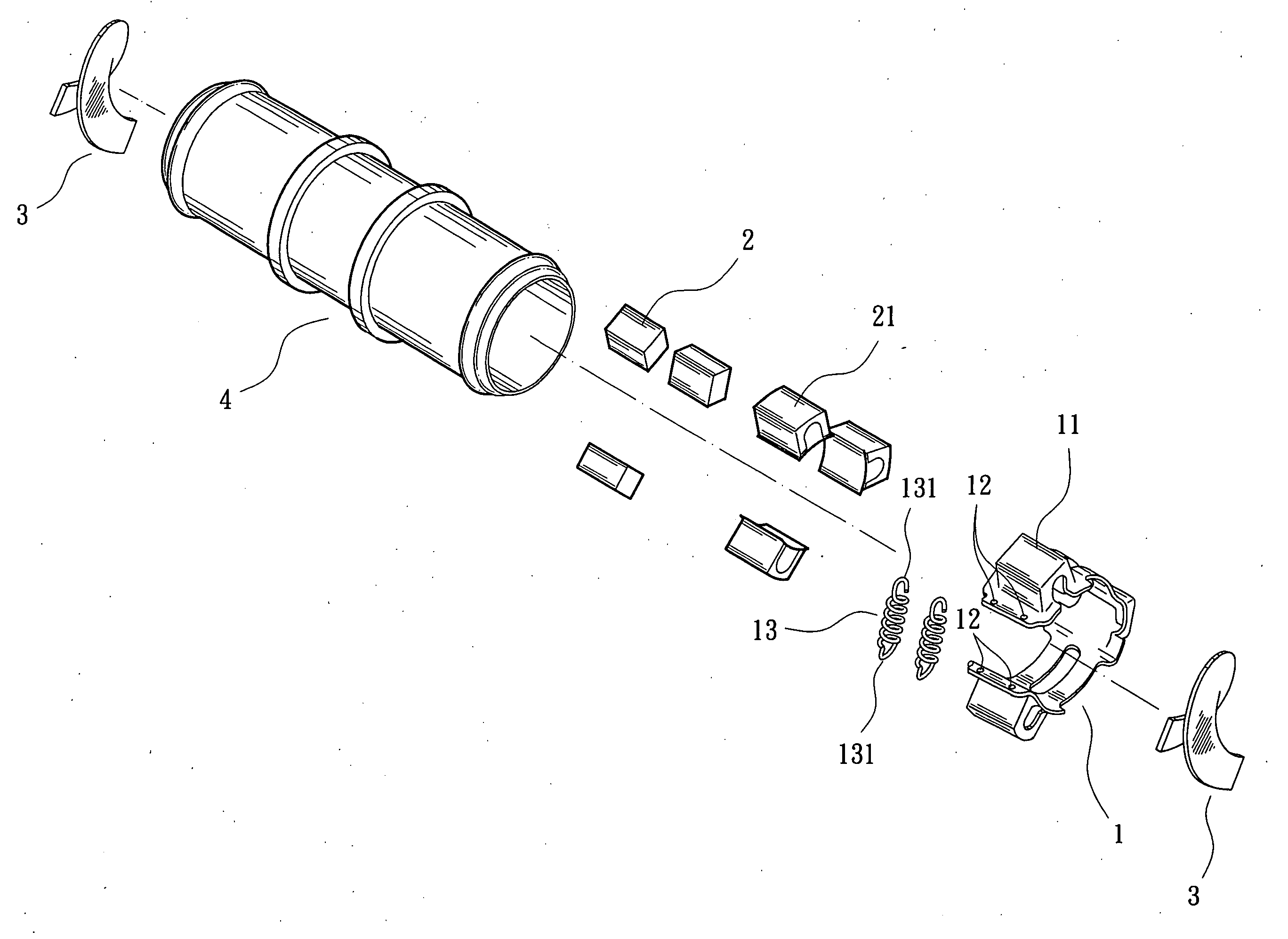
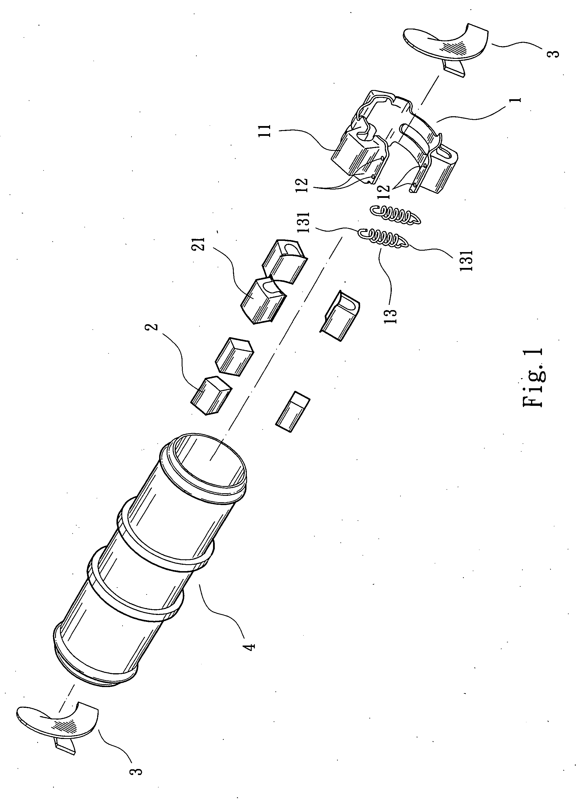
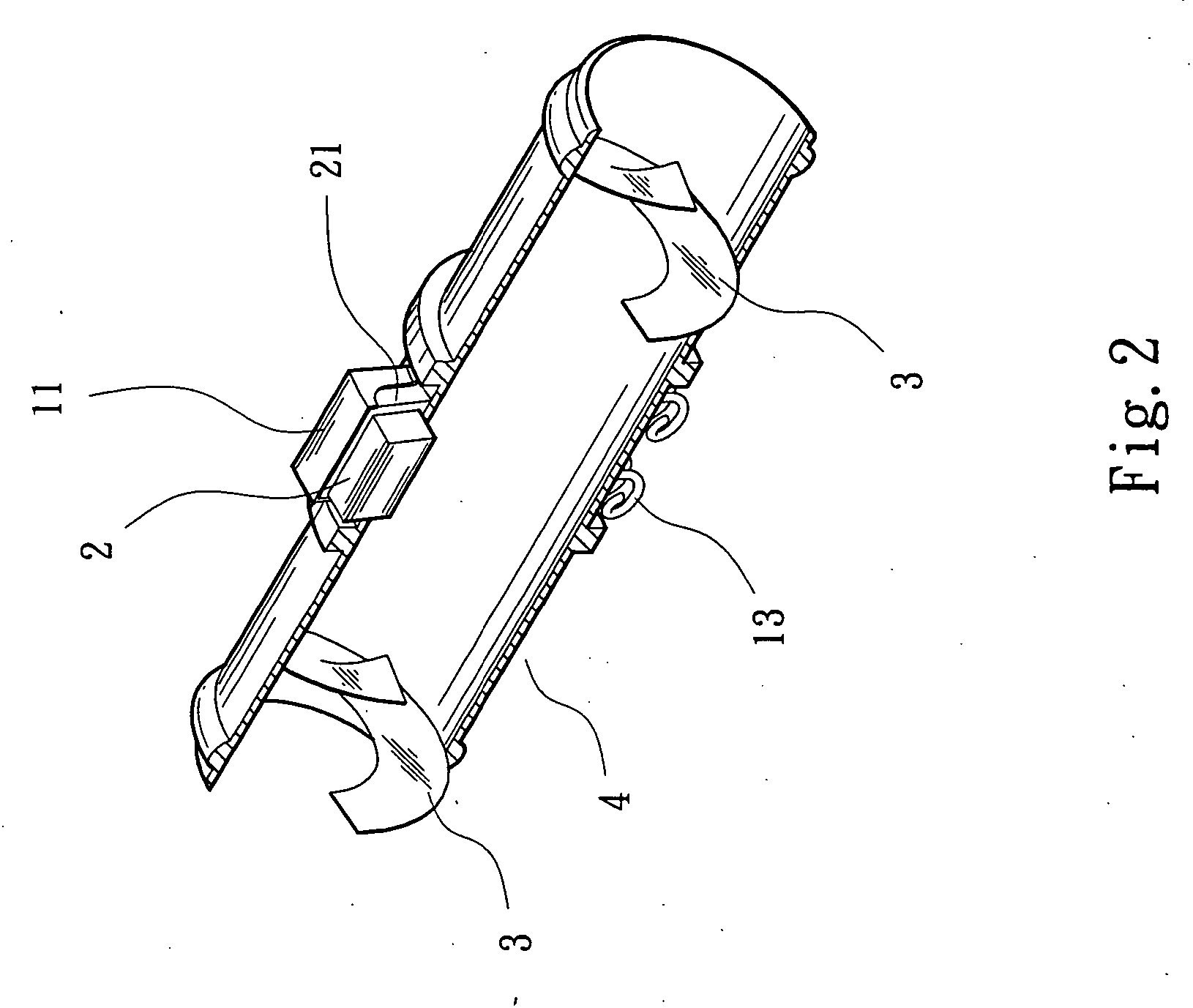
[0017] Please refer to FIGS. 1 to 3. The fluid-magnetizing device of the present invention includes a magnetic collar 1, several magnetic elements 2 and spiral flow-guiding plates 3. The magnetic collar 1 is an arced body made from magnetic conductive materials. Each end of the magnetic collar 1 is formed with at least one hole 12. Multiple outer casings 11 are disposed on a middle section of the magnetic collar 1. The magnetic elements 2 are individual magnetic bodies capable of producing magnetic lines (such as magnets). Each magnetic element 2 is fitted in an inner casing 21 without magnetic conductivity. Then the inner casing 21 with the magnetic element 2 is accommodated in the outer casing 11. The inner casing 21 serves to fasten and firmly locate the magnetic element 2 in the outer casing 11. The hook sections 131 of two ends of at least one resilient member 13 (spring) are respectively hooked between the holes 12 of the two ends of the magnetic collar 1. Therefore, the two e...


PUM

PropertyMeasurementUnit
circumferenceaaaaaaaaaa
magneticaaaaaaaaaa
magnetic conductivityaaaaaaaaaa

Abstract

A fluid-magnetizing device including an arced magnetic collar on which multiple outer casings are disposed. The outer casings are made from magnetic shield material. Multiple magnetic elements are accommodated in the outer casings of the magnetic collar. The magnetic collar has two ends between which multiple resilient members are connected for conveniently and firmly locating the magnetic collar around a fluid pipeline. At least one spiral flow guiding plate is disposed inside the fluid pipeline for guiding the fluid to spirally flow through the fluid pipeline. Accordingly, the contact time between the fluid and the magnetic lines is prolonged. In addition, the multiple magnetic elements are separately arranged to enhance and extend the magnetic lines so as to more efficiently magnetize the fluid in the fluid pipeline.

Description

BACKGROUND OF THE INVENTION [0001] The present invention is related to an improved fluid-magnetizing device including multiple separately arranged magnetic elements for providing dense magnetic lines. In addition, the fluid-magnetizing device is able to make a fluid spirally flow through a fluid pipeline under the action of the dense magnetic lines so that the fluid can be more efficiently magnetized. [0002] The magnetic lines of a magnetic body (magnet) are able to magnetize a fluid such as water to stabilize the molecules of the water. The stabilized water serves to strengthen human cells / tissues and enhance metabolism. This theory has been gradually realized and accepted by peoples. Various products for magnetizing fluids have been developed. It is known that the shortest path of the magnetic lines is between the two different magnetic poles. Also, the magnetic lines will not intersect each other. In addition, the farther the magnetic lines are away from the magnetic poles, the t...

Claims


Application Information

Patent Timeline
Patent Type & Authority Applications(United States)
IPC IPC(8): C02F1/48C02F1/00
CPCC02F1/482C02F2301/026C02F2301/024
Inventor CHANG, JEN-PEN
Owner CHANG JEN PEN
Why Eureka
Try Eureka