Eureka AIR delivers breakthrough ideas for toughest innovation challenges, trusted by R&D personnel around the world.

Heater that attaches electronic component to and detaches the same from substrate

a technology of electronic components and substrates, applied in the direction of ohmic-resistance heating, sustainable manufacturing/processing, final product manufacturing, etc., can solve problems such as insufficient heating, and achieve the effect of high-density mounting

Inactive Publication Date: 2006-10-19
FUJITSU LTD
View PDF10 Cites 20 Cited by
  • Summary
  • Abstract
  • Description
  • Claims
  • Application Information

AI Technical Summary

Benefits of technology

[0013] Accordingly, it is an exemplary object of the present invention to provide a heater, an electronic apparatus and substrate having the heater, a substrate mounted with the electronic component, and an electronic apparatus that includes the mounted substrate, which sufficiently protect a surrounding electronic components from the heat during reflow and rework, and realize the high-density mounting.
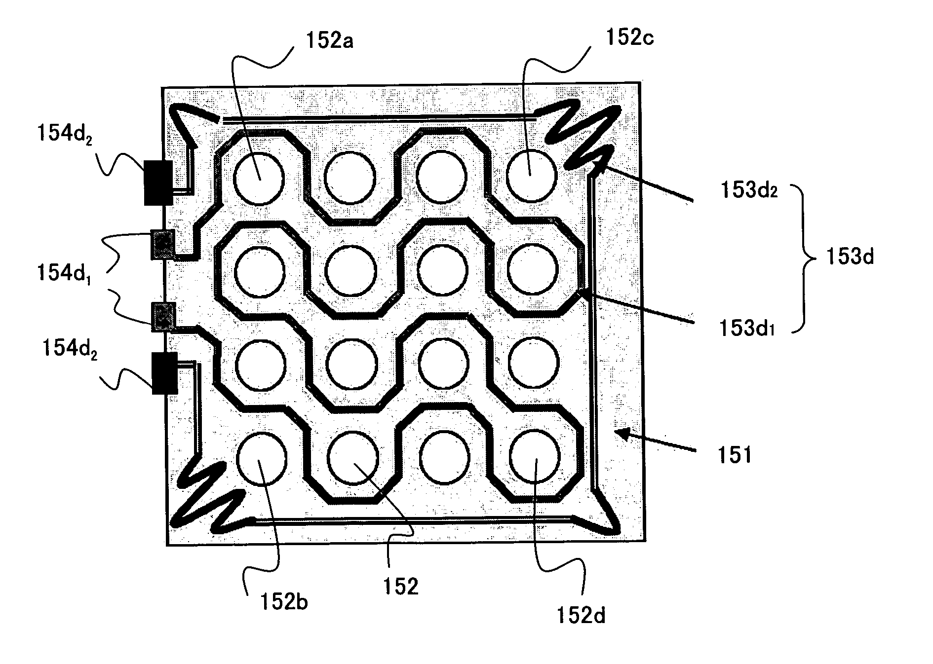
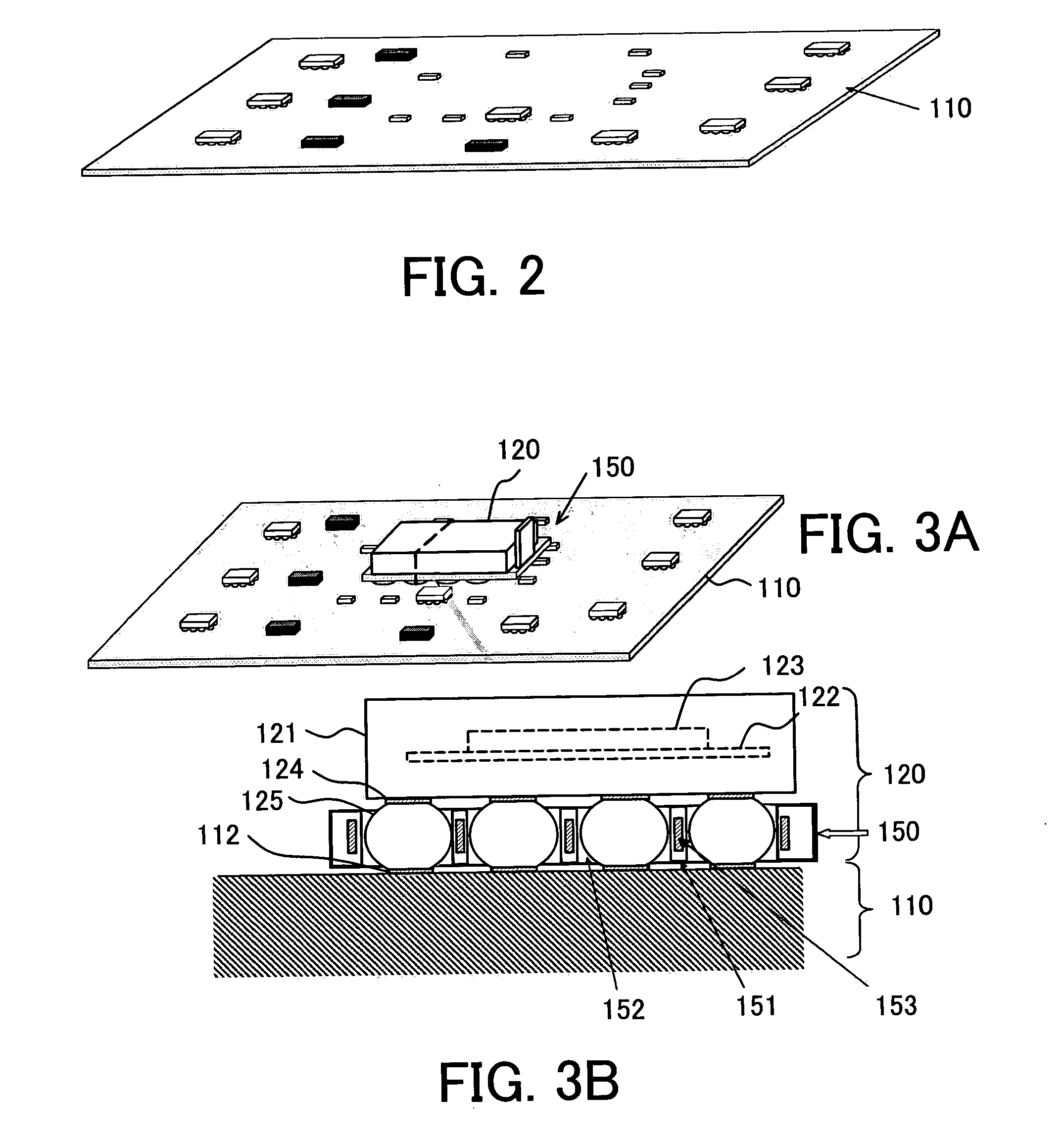
[0016] The heater may further include an adiabatic member between the heating element and the electronic component. This configuration can reduce the thermal damages or deteriorations of the electronic component. Preferably, the heating element is arranged near a plane that passes through centers of the plural soldering balls. This arrangement can efficiently heat the plural soldering balls uniformly. The heater may further include a power supply part that can be electrically connected to and disconnected from the heating element, the power supply part electrifying the heating element. Thereby, the power supply part does not have to be placed on the substrate. This power supply part may be shared among plural heaters.
[0017] An electronic component according to another aspect of the present invention that has a ball grid array structure and can be mounted on a substrate includes a body that accommodates an electronic circuit element that can operate on the substrate, a soldering ball to be soldered on the substrate, and the above heater which melts the soldering ball. This electronic component exhibits the operations of the above heater, and facilitates handling because it is integrated with the heater. The heater may be located at the same side as or at an opposite side to the soldering ball with respect to the body. When it is provided at the opposite side, the accommodation part of the heater may be omitted.
[0018] A substrate according to another embodiment includes a substrate body that can mount an electronic component that has a ball grid array structure, a footprint provided on the substrate body and connected to the electronic component, and the above heater, provided around the footprint, which melts soldering ball having the ball grid array structure. This substrate exhibits the operations of the above heater, and facilitates handling because it is integrated with the heater. The heater may further include an adiabatic member between the heating element and the electronic component. Solder may be filled between the heating elements and on the footprint. Since a user does not have to fill the soldering paste on the footprint, the operability improves.

Problems solved by technology

The second pattern may have a dense pattern at a corner of the plural soldering balls, because the heat is likely to escape particularly from the corners of plural soldering balls, causing insufficient heating.

Method used


Image

  • Heater that attaches electronic component to and detaches the same from substrate
  • Heater that attaches electronic component to and detaches the same from substrate
  • Heater that attaches electronic component to and detaches the same from substrate

Examples


Embodiment Construction

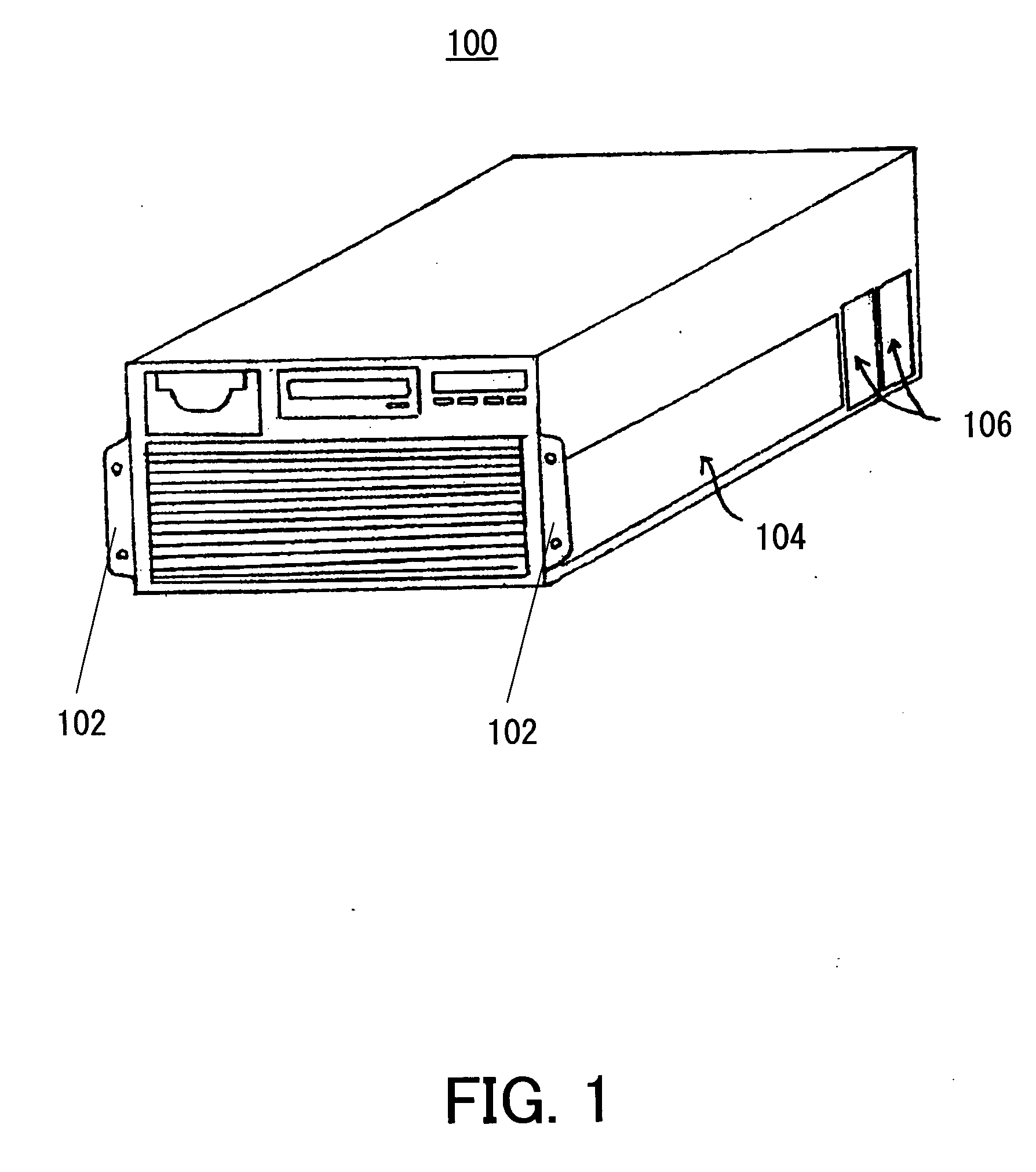
[0048] Referring now to the accompanying drawings, a description will be given of an electronic apparatus 100 according to one embodiment of the present invention. Here, FIG. 1 is a schematic perspective view of the electronic apparatus 100. As shown in FIG. 1, the electronic apparatus 100 is illustratively implemented as a rack mount type UNIX server. The electronic apparatus 100 is screwed onto a rack (not shown) by a pair of brackets 102, and includes a printed board 110 in a housing 104. Fan modules 106 are provided in the housing 104. The fan module 106 rotates a built-in cooling fan to generate the airflow, and compulsorily cools a heat sink in the housing 104.

[0049] The printed board 110 includes a BGA package (or an electronic component) 120, a heater 150, plural block plates (not shown) used to insert a memory card, and a connector (not shown) with an external apparatus, such as a hard disc drive (“HDD”) and a local area network (“LAN”), etc. The printed board 110 includes...


PUM


Abstract

A heater that attaches an electronic component having a ball grid array structure to and detaches the electronic component from a substrate on which the electronic component operates includes a body fixed onto the electronic component, and a heating element, provided on the body, which heats and melts soldering balls having the ball grid array structure when receiving power supply.

Description

[0001] This application claims a right of foreign priority based on Japanese Patent Application No. 2005-116518, filed on Apr. 14, 2005, which is hereby incorporated by reference herein in its entirety as if fully set forth herein. BACKGROUND OF THE INVENTION [0002] The present invention relates generally to an attachment of the electronic component to and a detachment of the same from a substrate, and more particularly to an apparatus that attaches a ball grid array (“BGA”) package to and detaches the same from a printed board. [0003] Along with the recent spreading smaller and higher-performance electronic apparatuses, a demand for providing an electronic apparatus that realizes a high-density mounting has remarkably increased. The BGA package has been conventionally proposed to meet this demand. In general, the BGA package is mounted with an IC or LSI that serves as a CPU, and one type of a package board soldered to a printed board (also referred to as a “system board” or “mother...

Claims


Application Information

Patent Timeline
Patent Type & Authority Applications(United States)
IPC IPC(8): H05B1/00
CPCH05K1/0212H05K3/3436H01L2224/16225H05K2203/176H01L24/799H05K2201/10734H01L2924/00011H01L2924/00014Y02P70/50H01L2224/0401
Inventor TAKADA, RIETSUBONE, KENICHIRO
Owner FUJITSU LTD
Why Eureka
Eureka Blog
Learn More