Waste heat utilizing system

a technology of utilizing system and waste heat, which is applied in the direction of engine starters, lighting and heating apparatus, heating types, etc., can solve the problems of high cost, reduced service life, and reduced service life of engine cooling water, so as to achieve low cost

Inactive Publication Date: 2006-10-19
DENSO CORP
View PDF4 Cites 31 Cited by
  • Summary
  • Abstract
  • Description
  • Claims
  • Application Information

AI Technical Summary

Benefits of technology

[0007] The present invention is made, therefore, in view of the foregoing problem, and has an object to provide a waste heat utilizing system, which is low in cost by eliminating a three-way valve.
[0009] It is a further object of the present invention to provide a waste heat utilizing system, in which an operating rate of an electrical pump is reduced to suppress consumption of electric power.

Problems solved by technology

According to the above conventional waste heat utilizing system, however, the water temperature stored in the tank may become lower than that of the engine cooling water at starting the engine operation, for example, when the engine has not been operated for a long period.
In such a situation, there is a problem that the temperature increase of the engine cooling water is prevented by the hot water storage tank, if the engine cooling water is circulated into and through the hot water storage tank.
However, such a system has a disadvantage that the cost thereof becomes high due to the three-way valve.

Method used


Image

  • Waste heat utilizing system
  • Waste heat utilizing system
  • Waste heat utilizing system

Examples


first embodiment

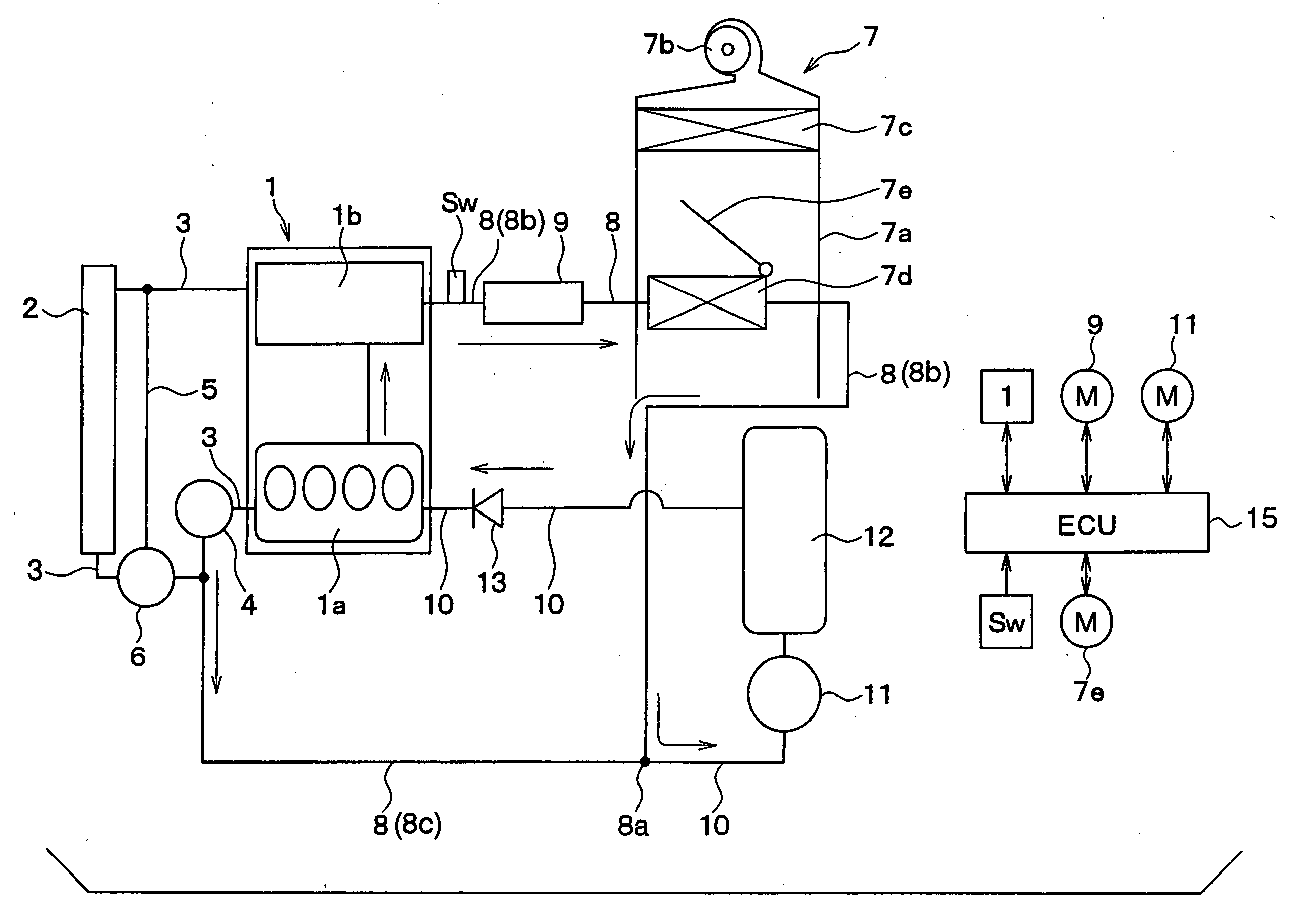
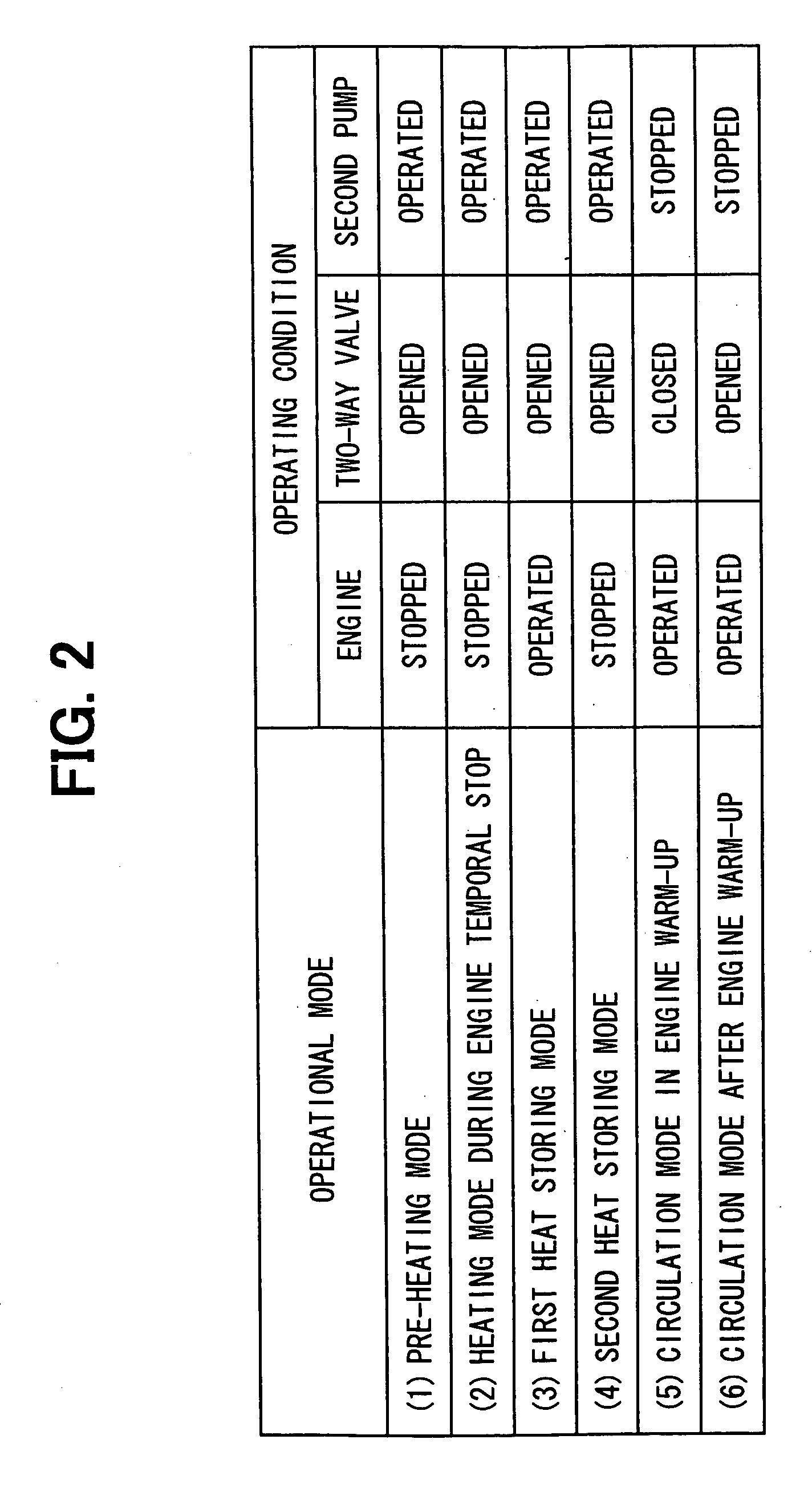
[0033] A first embodiment of the present invention will be explained. FIG. 1 shows a schematic system structure for a waste heat utilizing system for an automotive engine according to a first embodiment of the present invention, whereas FIG. 2 is a table showing various operational modes of the system shown in FIG. 1.

[0034] In FIG. 1, an internal combustion engine 1 produces a driving power for driving a vehicle, wherein the engine operation is automatically stopped when a certain operational condition for an engine stop is met, whereas the engine operation is automatically re-started when a certain operational condition for an engine re-start is satisfied. For example, the engine operation is stopped when the vehicle temporally stops due to a red traffic lamp, and re-started when a vehicle driver operates the vehicle to move again.

[0035] The engine 1 is a water cool type engine, in which a water jacket (not shown) is formed in a cylinder block 1a and a cylinder head 1b for circul...

second embodiment

[0071] A second embodiment of the present invention will be explained. FIG. 6 shows a schematic system structure for a waste heat utilizing system for an automotive engine according to a second embodiment of the present invention, whereas FIG. 7 is a table showing various operational modes of the system shown in FIG. 6.

[0072] In the second embodiment, the two-way valve 9 of the first embodiment is eliminated. As shown in FIG. 7, however, the operational modes of the second embodiment (the operational conditions of the engine 1 and the second pump 11) are the same to those of the first embodiment (FIG. 2).

[0073] The fluid flow of the engine cooling water in the circulation mode in the engine warm-up operation is different from that of the first embodiment, because the two-way valve 9 of the first embodiment is eliminated in this second embodiment.

[0074]FIG. 6 shows the fluid flow of the engine cooling water in the circulation mode of the engine warm-up operation. The engine coolin...

third embodiment

[0078] A third embodiment of the present invention will be explained with reference to FIGS. 8 to 13. A system structure of the third embodiment differs from the first embodiment, in that the check valve 13 for allowing the engine cooling water to flow only in one direction (the direction of the pumped out water by the second pump 11) is provided in the heat storage tank 12, and an ON-OFF valve 14 is provided in parallel with the check valve 13 for opening and closing a fluid passage in the heat storage tank 12 in accordance with the temperature of the engine cooling water.

[0079]FIG. 9 is a cross sectional view showing a structure of the heat storage tank 12, and FIG. 10 is an enlarged cross sectional view showing the check valve 13 and the ON-OFF valve 14.

[0080] As shown in FIG. 9, the heat storage tank 12 has a main tank body 121, which is made of such material having a high corrosion resistive characteristic, such as stainless steel. The main tank body 121 comprises an inside t...


PUM


Abstract

A main cooling circuit is formed by an engine, a radiator and a first pump. A hot water circuit is formed by the engine, a heater core and the first pump. A heat storing water circuit is connected between a bifurcating point of the hot water circuit and the engine, wherein a second pump and a heat storage tank are provided in the heat storing water circuit. Engine cooling water stored in the heat storage tank is circulated by the second pump, so that the hot water is supplied to the engine before the engine operation is started. The engine cooling water is also circulated by the second pump during the engine operation, so that hot water is stored in the heat storage tank.

Description

CROSS REFERENCE TO RELATED APPLICATION [0001] This application is based on Japanese Patent Application Nos. 2005-119581 filed on Apr. 18, 2005, and 2006-24288 filed on Feb. 1, 2006, the disclosures of which are incorporated herein by reference. FIELD OF THE INVENTION [0002] The present invention relates to a waste heat utilizing system for an automotive engine for facilitating a warming-up operation of a water cool internal combustion engine, and more particularly relates to a waste heat utilizing system for an automotive engine having a hot water storage tank for an engine cooling water. BACKGROUND OF THE INVENTION [0003] A waste heat utilizing system for a water cool internal combustion engine is known in the art, in which high temperature engine cooling water (hot water) circulating in an engine cooling circuit is stored in a hot water tank, the stored hot water is supplied to the engine by an electrical pump shortly before starting an engine operation in the next time in order t...

Claims


Application Information

Patent Timeline
Patent Type & Authority Applications(United States)
IPC IPC(8): B60H1/22
CPCB60H1/00492B60H1/04F01P7/165F01P11/20F02N19/10F01P2005/125F01P2007/146F01P2011/205F01P2060/08F01P2005/105
Inventor HASHIMURA, NOBUYUKIMIYATA, YOSHIOOGAWA, SHINJIYANAGISAWA, YUSUKETOYOSHIMA, TAKASHI
Owner DENSO CORP
Why Eureka
Try Eureka