Particle detection by electron multiplication

Inactive Publication Date: 2006-10-19
ETP ION DETECT PTY LTD
View PDF2 Cites 13 Cited by
  • Summary
  • Abstract
  • Description
  • Claims
  • Application Information

AI Technical Summary

Benefits of technology

[0018] A further objective of the invention is to provide a particle detector with relatively large sensitive area as compared to a relatively small overall size and without the need for electron focussing as p

Problems solved by technology

Such artefacts are usually seen as unwanted small peaks in the mass spectrum, which are not coincident with the primary signal associated with the incoming ion, and thus add confusion when interpreting the spectrum.
Devices utilising combined electrostatic an

Method used


Image

  • Particle detection by electron multiplication
  • Particle detection by electron multiplication

Examples


Embodiment Construction

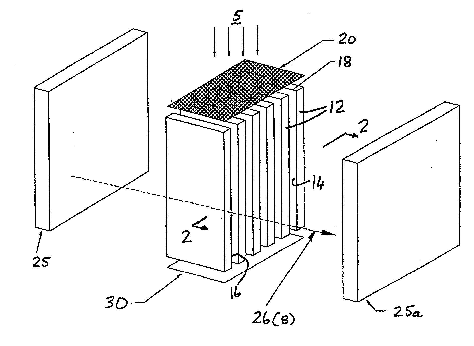
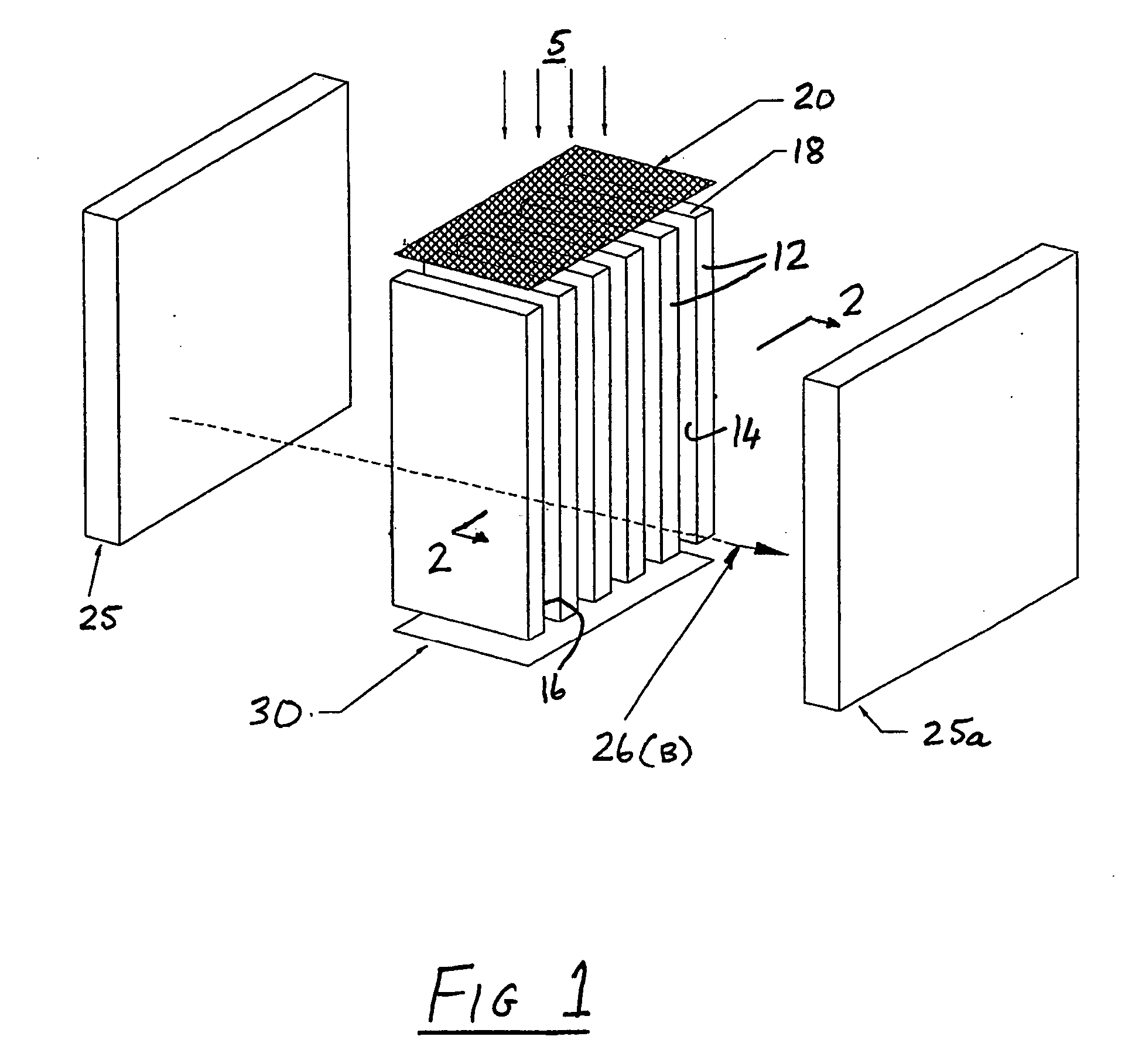
[0034] The illustrated electron multiplier particle detector includes a set of spaced, uniformly dimensioned plate structures 12 of elongated rectangular cross-section. The wider faces of each structure define respective flat faces 14, 16 coated in electrically resistive material. The narrower face at the top forms an impact surface segment 18 chosen to respond to each impacting particle, in this case ion 5, to be detected by generating a secondary electron.

[0035] Surface segments 18 are coplanar and so provide a segmented impact surface for ions 5. Faces 14 are parallel, and are electron emissive so as to define a continuous dynode plate, effectively a continuous array of dynode segments. Faces 16 are opposed to and parallel to dynode plates 12 and serve a purpose to be explained further below. Faces 16 are hereinafter referred to as attractor plates.

[0036] A combined electrostatic and magnetic field is provided for controlling the trajectories of secondary electron streams throu...


PUM


Abstract

An electron multiplier detector includes cathode structure defining a plurality of spaced co-planar impact surface segments on which particles impact. These surface segments each have a finite probability of generating at least one electron for each impacting particle having predetermined characteristics. The detector further includes respective sets of electron multiplication dynode segments associated with the impact surface segments, the sets being arranged as substantially parallel arrays extending behind the impact surface segments, and respective means for generating electrostatic and magnetic fields in a space extending from the impact surface segments past the dynode segments, whereby respective streams of electrons cascade and multiply successively along the arrays of dynode segments. Collector structure is provided to receive and detect the streams of electrons downstream of the last dynode segments in the arrays.

Description

FIELD OF THE INVENTION [0001] This invention relates generally to the detection of particles and is concerned in particular with enhancements of electron multiplier configurations for this purpose. [0002] In the context of this specification, a “particle” may be an ion or other charged particle, a neutral particle or a photon, that is capable of causing an impacted surface to generate an electron. A common application of electron multipliers, however, is the detection of specific ions, for example in mass spectrometers, and hence for convenience, particles to be detected will sometimes be referred to herein as ions. BACKGROUND ART [0003] To optimise the usefulness or performance of an electron multiplier, it is often desirable to have a large sensitive input area so that particles can be detected which are incident over a large area. [0004] As well as enabling the detector to have a large sensitive input area, a number of additional requirements for the detector will be necessary if...

Claims


Application Information

Patent Timeline
IPC IPC(8): G01K1/08
CPCG01T1/28H01J43/14
Inventor STRESAU, RICHARDHUNTER, KEVINSHEILS, WAYNERAFFIN, PETERBENARI, YAIR
Owner ETP ION DETECT PTY LTD
Why Eureka
Try Eureka