RFID tag and RFID reader for anti-collision and operating method thereof

a technology of radio frequency identification and rfid reader, which is applied in the field of rfid (radio frequency identification) tags and rfid readers with anticollision functions, and an operating method thereof, which can solve the problems of increasing the idling time of rfid tags, the collision of rfid systems, and the inefficiency of rfid tags

Inactive Publication Date: 2006-10-19
SAMSUNG ELECTRONICS CO LTD
View PDF10 Cites 22 Cited by
  • Summary
  • Abstract
  • Description
  • Claims
  • Application Information

AI Technical Summary

Benefits of technology

[0022] The controlling part may control the reader transmitting part to re-retransmit the tag recognition signal, after the mode switch signal is transmitted through the reader transmitting part.
[0023] According to yet another aspect of the present invention, an operation method of a RFID (radio frequency identification) reader for anti-collision may be provided, comprising transmitting a tag recognition signal to one or more RFID tags, receiving tag data from the RFID tags in accordance with the tag recognition signal, and when the tag data is received, generating a mode switch signal for a RFID tag corresponding to the received tag data and transmitting through the reader transmitting part.

Problems solved by technology

However, the RFID system exhibits a problem with collision between the tags, especially when there are a plurality of RFID tags within a transmission range where the RFID reader can recognize the RFID tag, and thus, all the tags respond to the signal of the RFID reader.
If the above-mentioned suggestions are applied in these devices, the idling time of the RFID tags increases which is quite inefficient especially when the number of RFID tags being used are few.

Method used


Image

  • RFID tag and RFID reader for anti-collision and operating method thereof
  • RFID tag and RFID reader for anti-collision and operating method thereof
  • RFID tag and RFID reader for anti-collision and operating method thereof

Examples


Embodiment Construction

[0033] Certain exemplary embodiments of the present invention will be described in greater detail with reference to the accompanying drawings.

[0034] In the following description, same drawing reference numerals are used for the same elements even in different drawings. The matters defined in the description such as the detailed construction and elements are nothing but the ones provided to assist in a comprehensive understanding of the invention. Thus, it is apparent that the present invention can be carried out without those defined matters. Also, well-known functions or constructions are not described in detail since they would obscure the invention in unnecessary detail.

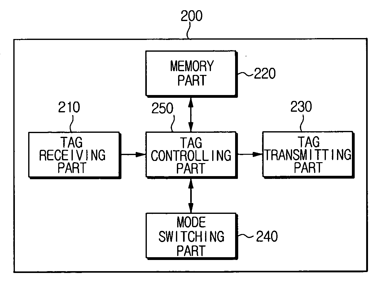
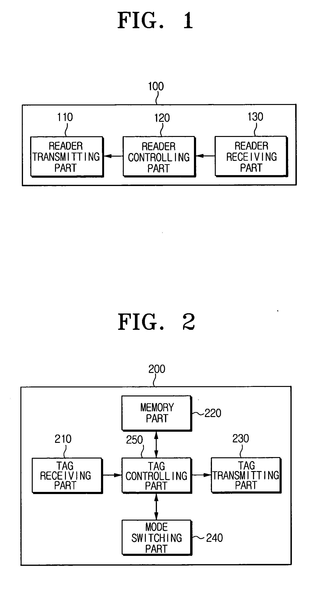
[0035]FIG. 1 is a block diagram of a RFID reader for anti-collision according to an exemplary embodiment of the present invention.

[0036] Referring to FIG. 1, a RFID reader 100 according to an exemplary embodiment of the present invention includes a reader transmitting part 110, a reader controlling part 120 and...


PUM


Abstract

A radio frequency identification (RFID) tag and a RFID reader for anti-collision, and an operation method thereof are provided. The RFID tag includes a tag receiving part for receiving a tag recognition signal from a RFID reader, a tag transmitting part for transmitting a response signal and a tag data in response to the tag recognition signal, a mode switching part for switching current mode into a predetermined mode, and a controlling part for causing the predetermined mode to be switched by the mode switching part, when the response signal is transmitted by a predetermined number of times by the tag transmitting part. Accordingly, when a few number of RFID tags are used, collision of tag data can be prevented at the RFID reader, and the RFID tags are rapidly recognized.

Description

CROSS-REFERENCE TO RELATED APPLICATIONS [0001] This application claims priority from Korean Patent Application No. 2005-31465, filed Apr. 15, 2005, in the Korean Intellectual Property Office, the disclosure of which is incorporated herein by reference. BACKGROUND OF THE INVENTION [0002] 1. Field of the Invention [0003] The present invention relates to a RFID (radio frequency identification) tag and a RFID reader with anti-collision function, and an operating method thereof. More particularly, the present invention relates to a RFID reader and a RFID tag for preventing collision between RFID tags in the situation where the number of RFID tags are few in number, and an operating method thereof. [0004] 2. Description of the Related Art [0005] A RFID (radio frequency identification) is one of the AIDC (Automatic identification and data capture) technologies, which contactlessly reads the data of the chip with a built-in microchip by using wireless frequency. [0006] Basically, a RFID sys...

Claims


Application Information

Patent Timeline
Patent Type & Authority Applications(United States)
IPC IPC(8): H04Q5/22
CPCG06K7/0008G06K19/0723G06K7/10019G02B23/00G09B27/04
Inventor YOON, HYUNG-MINKANG, WOO-SHIKKOO, SI-GYOUNGKOO, JI-HUNPARK, KYUNG-HO
Owner SAMSUNG ELECTRONICS CO LTD
Why Eureka
Try Eureka