Liquid crystal display device and production method thereof

a technology of liquid crystal display and display device, which is applied in the direction of static indicating device, non-linear optics, instruments, etc., can solve the problem of reducing the visibility of displayed images in a bright environment such as outdoors, and achieve the effect of improving the visibility of the liquid crystal display devi

Inactive Publication Date: 2006-10-19
TOSHIBA MATSUSHITA DISPLAY TECH
View PDF7 Cites 38 Cited by
  • Summary
  • Abstract
  • Description
  • Claims
  • Application Information

AI Technical Summary

Benefits of technology

[0009] With the configuration as above, as a result of providing the first insulating layers, each of which has spectral characteristics for one of at least three colors that comprise a first color, a second color, and a third color respectively corresponding to light's three primary colors, between the pixel electrodes and the first substrate of the array substrate, the portion of each pixel electrode of the array substrate that does not face the corresponding second insulating layer of the counter substrate serves as a region where image display

Problems solved by technology

However, because the liquid crystal device described above is a nonemissive display devi

Method used


Image

  • Liquid crystal display device and production method thereof
  • Liquid crystal display device and production method thereof

Examples


Embodiment Construction

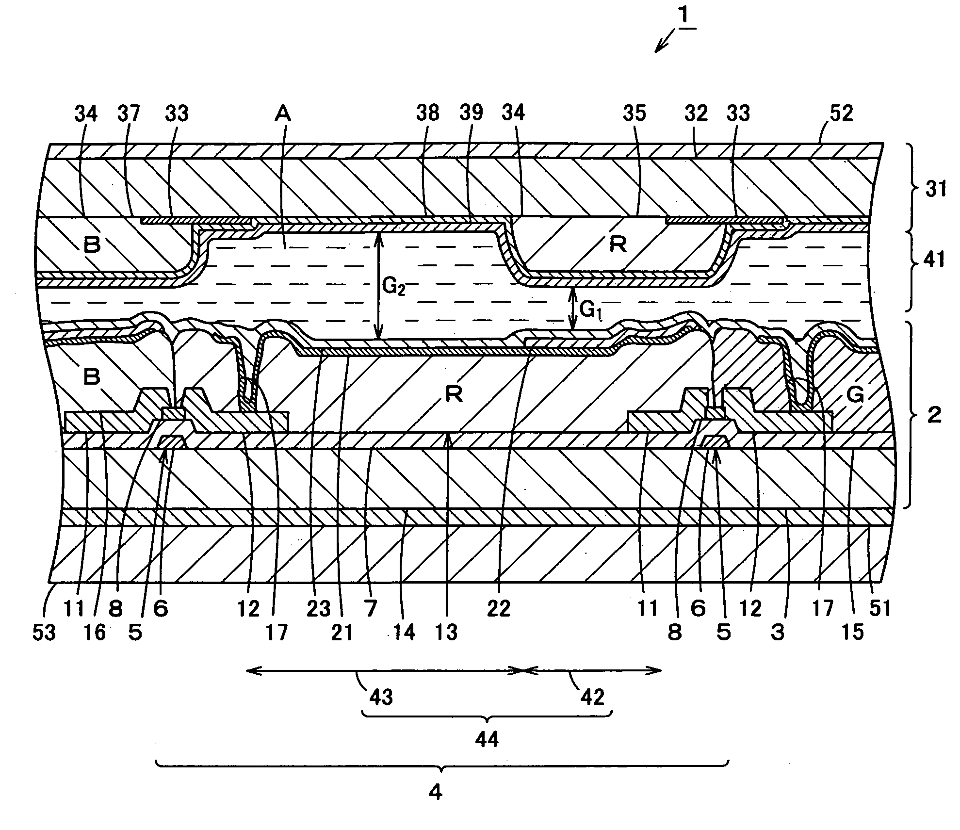
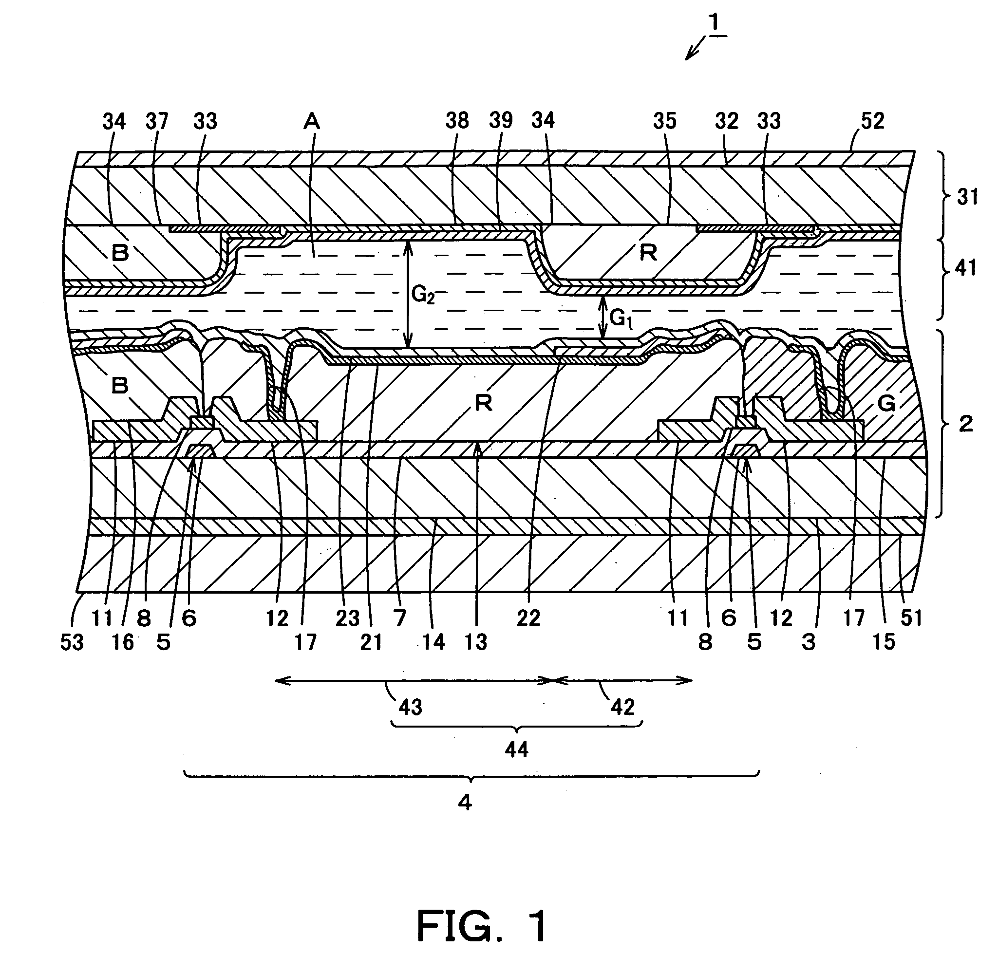
[0011] Next, the structure of a liquid crystal device according to an embodiment of the present invention is explained in detail, referring to FIG. 1. In the explanation hereunder, the term “the lateral direction” refers to the lateral direction as viewed in FIG. 1, and the terms “right” and “left”, are as viewed in FIG. 1. The term “the longitudinal direction” refers to the direction perpendicular to the lateral direction as seen from the top view.

[0012] In FIG. 1, numeral 1 denotes a liquid crystal element otherwise referred to as a liquid crystal device. The liquid crystal element 1 is a nonemissive display device of a multigap type. The liquid crystal element 1 is an active matrix type semi-transmissive liquid crystal panel and has a bottom gate type array substrate 2 in the shape of a generally rectangular flat plate. The array substrate 2 has a glass substrate 3, which may otherwise be referred to as a first substrate. The glass substrate 3 is a nearly transparent insulating ...


PUM


Abstract

Each pixel of an array substrate is provided with a reflective region and a transmittance region. A first color filter layer is provided between each pixel electrode and a gate insulating film of the array substrate. The first color filter layer of each pixel has spectral characteristics corresponding to the second color filter layer that is provided in association with the reflective region of the pixel. Each reflective region is a region where image display is enabled by light that passes through the corresponding second color filter layer and is reflected by its reflection layer. Each transmittance region is a region where image display is enabled by light that is emitted from a backlight and passes through the corresponding first color filter layer. Spectral separation by the first color filter layers and the second color filter layers enables the liquid crystal element to display an image.

Description

INCORPORATION BY REFERENCE [0001] The present application claims priority under 35 U.S.C. §119 to Japanese Patent Application No. 2005-119717 filed on Apr. 18, 2005. The content of the application is incorporated herein by reference in its entirety.FIELD OF THE INVENTION [0002] The present invention relates to a liquid crystal device having a liquid crystal layer disposed between an array substrate and a counter substrate. The invention further relates to a method of producing such a liquid crystal device. BACKGROUND OF THE INVENTION [0003] A conventional liquid crystal device of this type is widely used as a display of a laptop computer, a portable personal computer, or a word processor, because it not only can be made light and thin, but also operates with a low driving voltage as well as low power consumption, and also has features not apparent in a light emission type image display. There has been a noticeable trend, particularly recently, for active matrix type liquid crystal d...

Claims


Application Information

Patent Timeline
IPC IPC(8): G09G3/36
CPCG02F1/133371G02F1/133514G02F2203/09G02F2001/136222G02F1/133555G02F1/136222
Inventor MIDORIKAWA, TERUYUKI
Owner TOSHIBA MATSUSHITA DISPLAY TECH
Why Eureka
Try Eureka