Belt conveyance apparatus and image forming apparatus using such a belt conveyance apparatus

a technology of conveyance apparatus and belt, which is applied in the field of image forming apparatus to achieve the effect of correcting the deflection of the conveyance bel

Active Publication Date: 2006-10-19
RICOH KK
View PDF4 Cites 40 Cited by
  • Summary
  • Abstract
  • Description
  • Claims
  • Application Information

AI Technical Summary

Benefits of technology

[0022] According to the present invention, the driven roller is rotatably supported, and the driven roller support means is provided to movably support the driven roller in the thrust direction, and the drive roller and the end of the driven roller interfere with the conveyance belt so as to restrict a deflection of the conveyance belt in the thrust direction and the driven roller is movable in the thrust direction against the d

Problems solved by technology

However, with such a belt driving apparatus, since the support shaft of the driven roller engaged with a conveyance belt is restricted or fixed so as to not

Method used


Image

  • Belt conveyance apparatus and image forming apparatus using such a belt conveyance apparatus
  • Belt conveyance apparatus and image forming apparatus using such a belt conveyance apparatus
  • Belt conveyance apparatus and image forming apparatus using such a belt conveyance apparatus

Examples


first embodiment

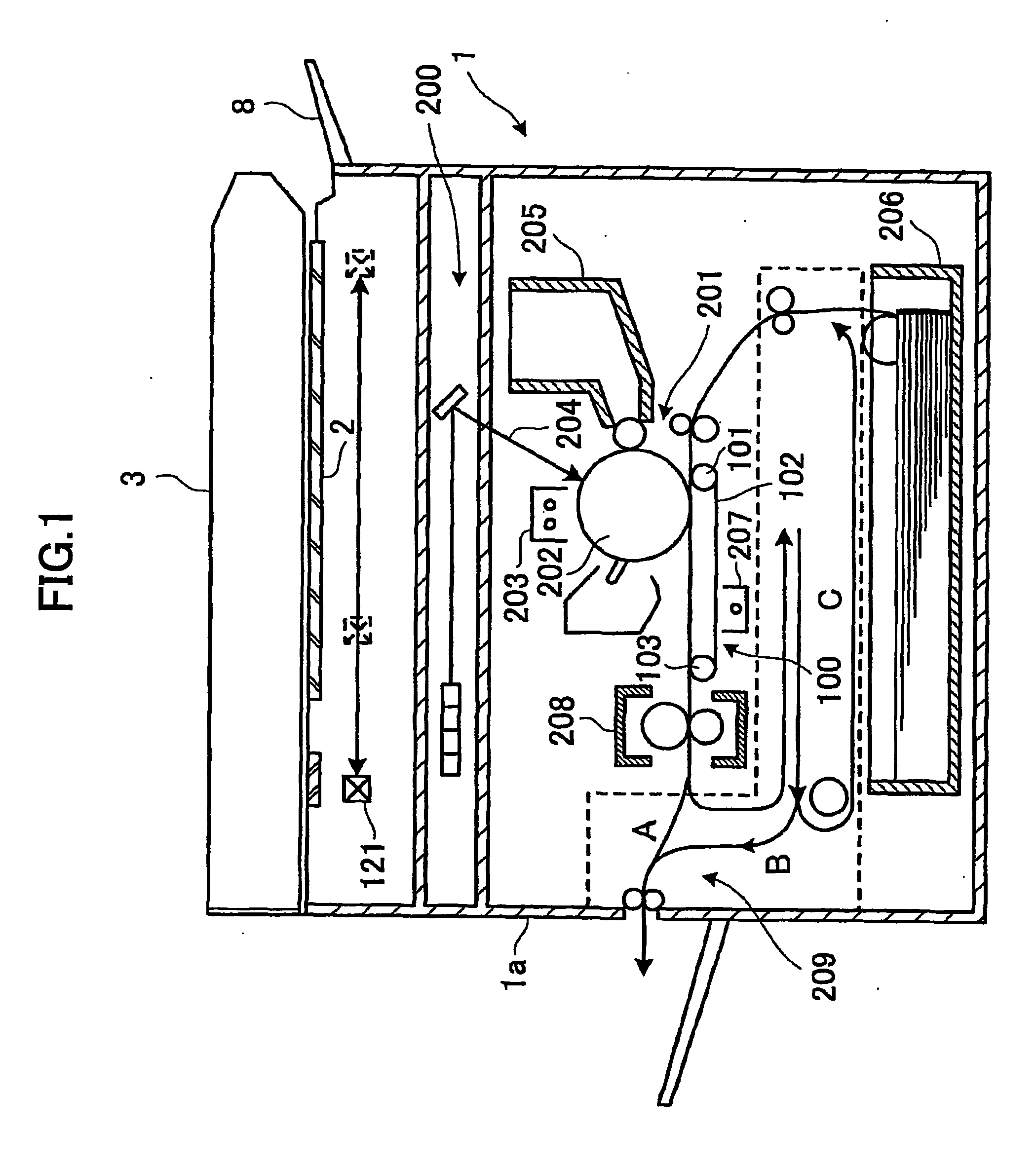
[0047]FIG. 1 shows an entire structure of a digital copy machine as an image forming apparatus to which a belt conveyance apparatus according to a first embodiment of the present invention is applied. It should be noted that the present invention is not limited to digital copy machines, and is applicable to wide variety of apparatuses if they have a belt conveyance part, such as a facsimile apparatus, a printer (including an inkjet printer), etc.

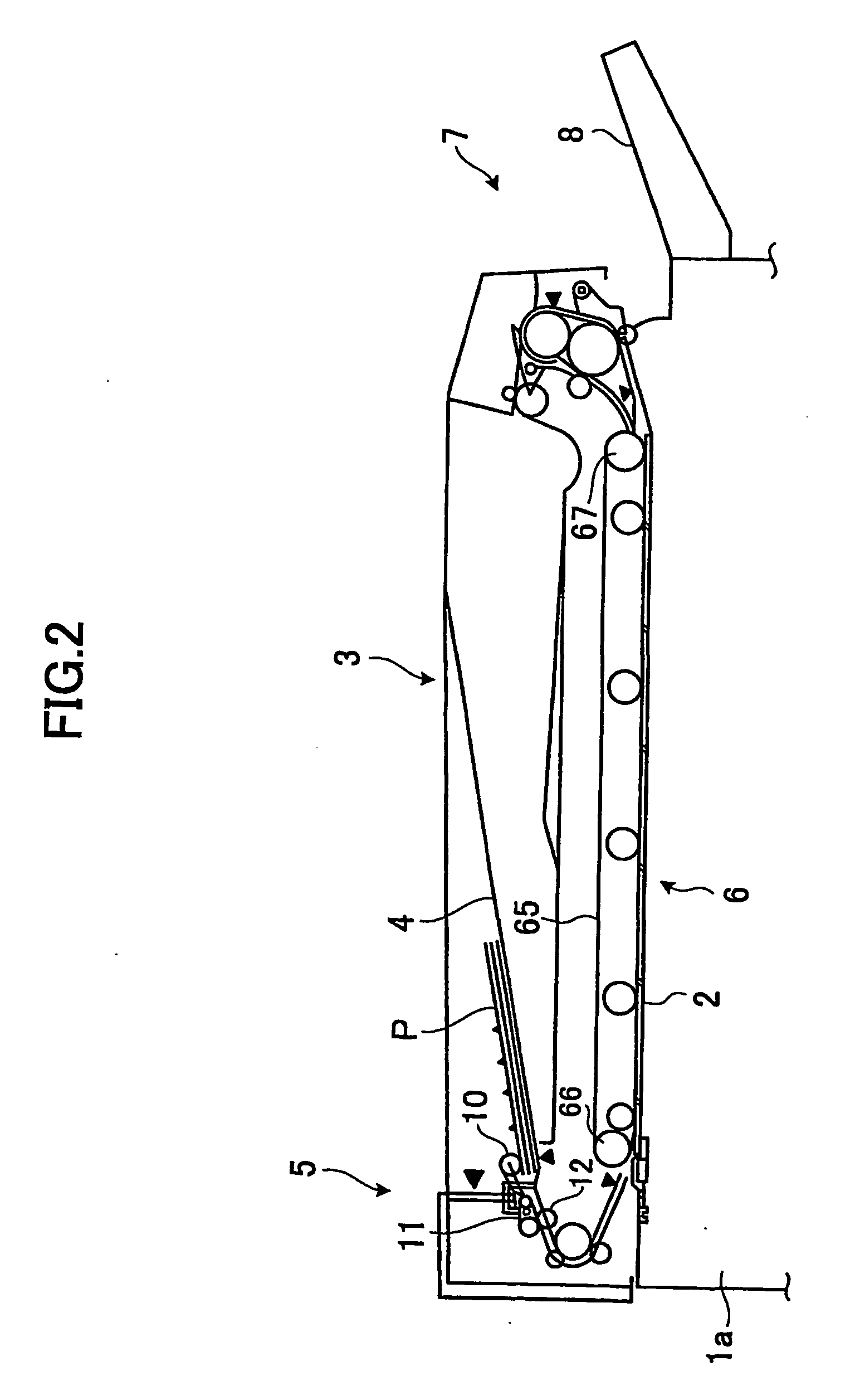
[0048] Provided on a top surface of a main body la of the digital copy machine 1 are a contact glass 2 and a slit glass having an area smaller than the contact glass 2. Additionally, an automatic document feeder 3 (hereinafter, may be abbreviated as “ADF”) is provided via a hinge mechanism (not shown) on the main body la of the digital copy machine 1 (in this example, it is placed on the contact glass 2 and slit glass). The ADF 3 is movable relative to the contact glass 2 and the slit glass so as to open or close a space above the contact g...

second embodiment

[0070] A digital copy machine according to a second embodiment of the present invention has the same structure as the digital copy machine according to the first embodiment of the present invention except for a part of the intermediate transfer part 100, and, thus, FIGS. 1, 2, 3 and 5A are used for the description of the second embodiment and the same component parts are given the same reference numerals.

[0071]FIG. 6 shows a plan view of a part of the intermediate transfer part of the digital copy machine according to the second embodiment of the present invention.

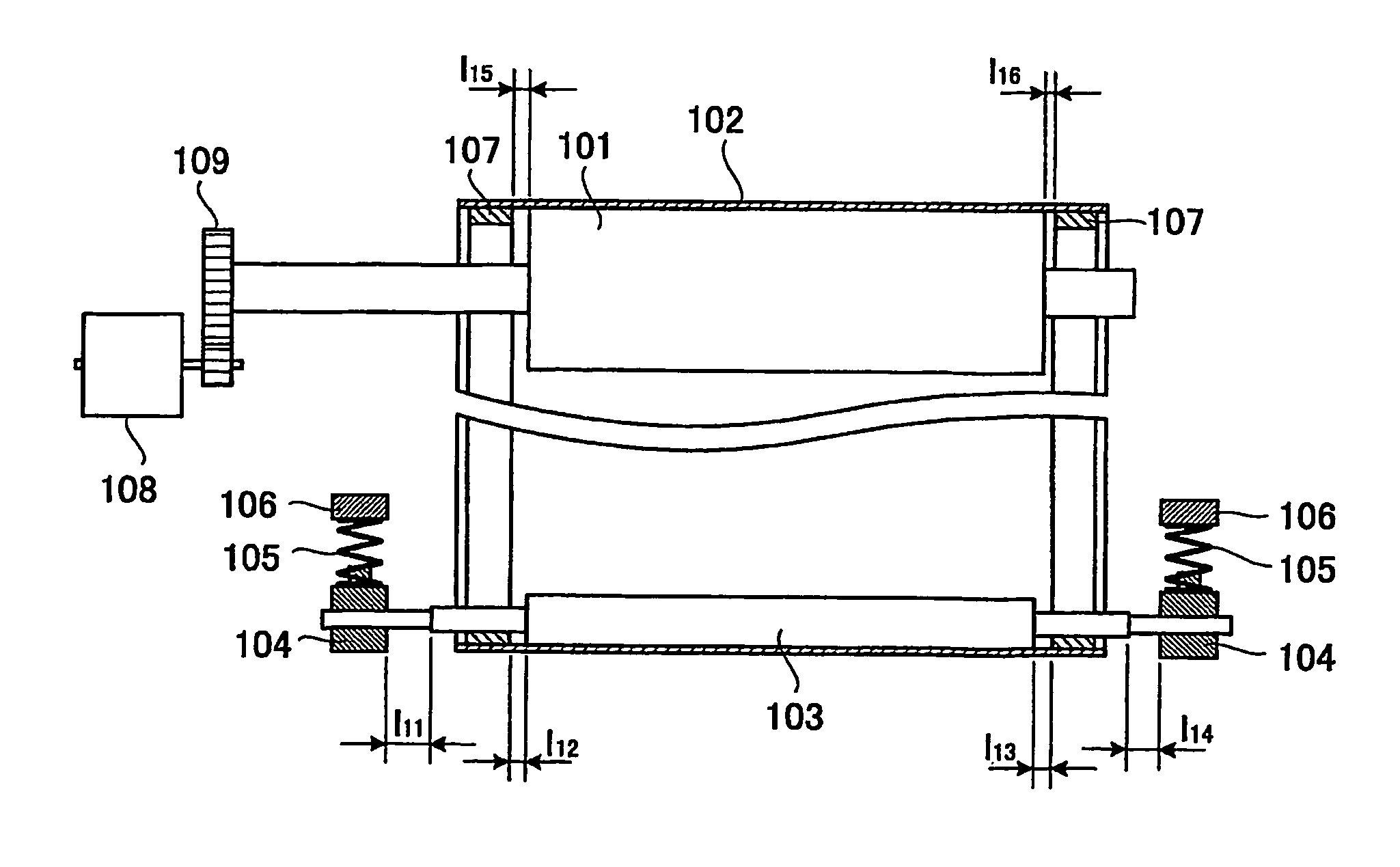
[0072] In FIG. 6, grooves 110 for receiving the beads 107 of the intermediate transfer belt 102 are formed on the circumferential surface the intermediate transfer belt drive roller 101. Here, the grooves 110 are formed on both sides of the intermediate transfer belt drive roller 110 in the direction of width. It should be noted that the operation shown in FIG. 5A is the same as the case where the movement of the beads 1...

third embodiment

[0077] A digital copy machine according to a third embodiment of the present invention has the same structure as the digital copy machine according to the first embodiment of the present invention except for a part of the intermediate transfer part 100, and, thus, FIGS. 1, 2, 3 and 5A are used for the description of the third embodiment and the same component parts are given the same reference numerals.

[0078]FIG. 7 shows a plan view of a part of an intermediate transfer part of the digital copy machine according to the third embodiment of the present invention. FIGS. 8A and 8B show a part of an intermediate transfer belt drive roller having a rotational member. FIGS. 8C and 8D show a part of an intermediate transfer belt drive roller having no rotational member.

[0079] In the intermediate transfer part 100, rotational members 121 each having a tapered corner are attached to both ends of the intermediate transfer belt drive roller 101. The rotational members 121 may interfere with t...


PUM


Abstract

In an intermediate transfer part (100), a bead 107 is formed on an inner side of an intermediate transfer belt (102), which is rotated by an intermediate transfer belt drive roller (101). Driven roller bearings (104a, 104b) support an intermediate transfer belt driven roller (103). The intermediate transfer belt driven roller (103) is movable in a thrust direction. Ends of the intermediate transfer belt driven roller (101) and the intermediate transfer belt driven roller (103) interfere with a bead (107) so as to restrict a deflection of the intermediate transfer belt in the thrust direction. The intermediate transfer belt driven roller (103) is movable in the thrust direction against a deflection of the intermediate transfer belt (102).

Description

TECHNICAL FIELD [0001] The present generally relates to image forming apparatuses and, more particularly, to an image forming apparatus using a belt conveyance apparatus provided with a drive roller, a driven roller and an endless belt engaged with the drive roller and the driven roller. cl BACKGROUND ART [0002] A conventional belt conveyance apparatus has an endless guide member in a part extending from an end surface of a conveyance roller on a conveyance belt so that the endless guide member is engaged with a partition plate provided on a side of ends of a drive roller and a driven roller (may be referred to as a follower roller or an idle roller) (for example, refer to patent document 1). According to the above structure, there is no stress generated in the endless guide member if the conveyance belt moves in a zigzag direction and a pressure force is exerted on the conveyance belt and an elongation occurs, and a flatness of the conveyance belt is maintained. [0003] Additionally...

Claims


Application Information

Patent Timeline
IPC IPC(8): G03G15/00B65H5/02
CPCB65G15/64B65G39/16B65H5/026B65H2404/2222G03G15/1615B65H2404/255G03G15/161G03G2215/00151B65H2404/253B65H5/02
Inventor MAKI, TSUNEOMISUMI, TOMIYOSHITSUKAMURA, KIYOSHIITOH, YOHICHIAOKI, HIDEO
Owner RICOH KK
Why Eureka
Try Eureka