Charged-particle beam instrument

a charge-particle beam and instrument technology, applied in instruments, heat measurement, therapy, etc., can solve the problems of oblique incidence on the surface of the workpiece, deterioration of deflection and lithography accuracy, and difficulty in increasing the electrode length of the second deflector b>16, so as to increase the electrode length increase the deflection voltage of the second deflector, and reduce the inside diameter of the electrod

Active Publication Date: 2009-04-21
JEOL LTD
View PDF6 Cites 0 Cited by
  • Summary
  • Abstract
  • Description
  • Claims
  • Application Information

AI Technical Summary

Benefits of technology

[0018]It is an object of the present invention to provide a novel charged-particle beam instrument designed to be capable of correcting deflection aberrations in the first deflector or oblique incidence without (i) increasing the electrode length of the second deflector, (ii) reducing the inside diameter of the electrode of the second deflector, or (iii) increasing the deflection voltage of the second deflector as much.
[0020]In this charged-particle beam instrument, the second deflector for canceling out the deflection aberrations in the first deflector or oblique incidence of the beam on the surface of the workpiece is placed ahead of the demagnifying lens. Consequently, the angle of deflection made by the second deflector is magnified by the demagnifying lens and so the deflection voltage applied to the second deflector can be suppressed to such a low level that the deflection speed of the deflector is not adversely affected.

Problems solved by technology

Furthermore, in such electron beam deflection, there is the problem of oblique incidence on the surface of the workpiece.
This deteriorates the accuracy of deflection and lithography.
However, in the optical system shown in FIG. 1, it is difficult to increase the electrode length of the second deflector 16 because of spatial restrictions.
Consequently, the problem that deposition of contaminants arises from scattering electrons tends to be produced more easily.
From this viewpoint, increasing the deflection voltage of the second deflector 16 greatly will result in a detrimental effect.

Method used


Image

  • Charged-particle beam instrument
  • Charged-particle beam instrument
  • Charged-particle beam instrument

Examples


Embodiment Construction

[0026]Embodiments of the present invention are hereinafter described in detail with reference to the drawings. The description of the embodiments centers on cancellation of aberrations for the sake of convenience of illustration; description of cancellation of oblique incidence is omitted.

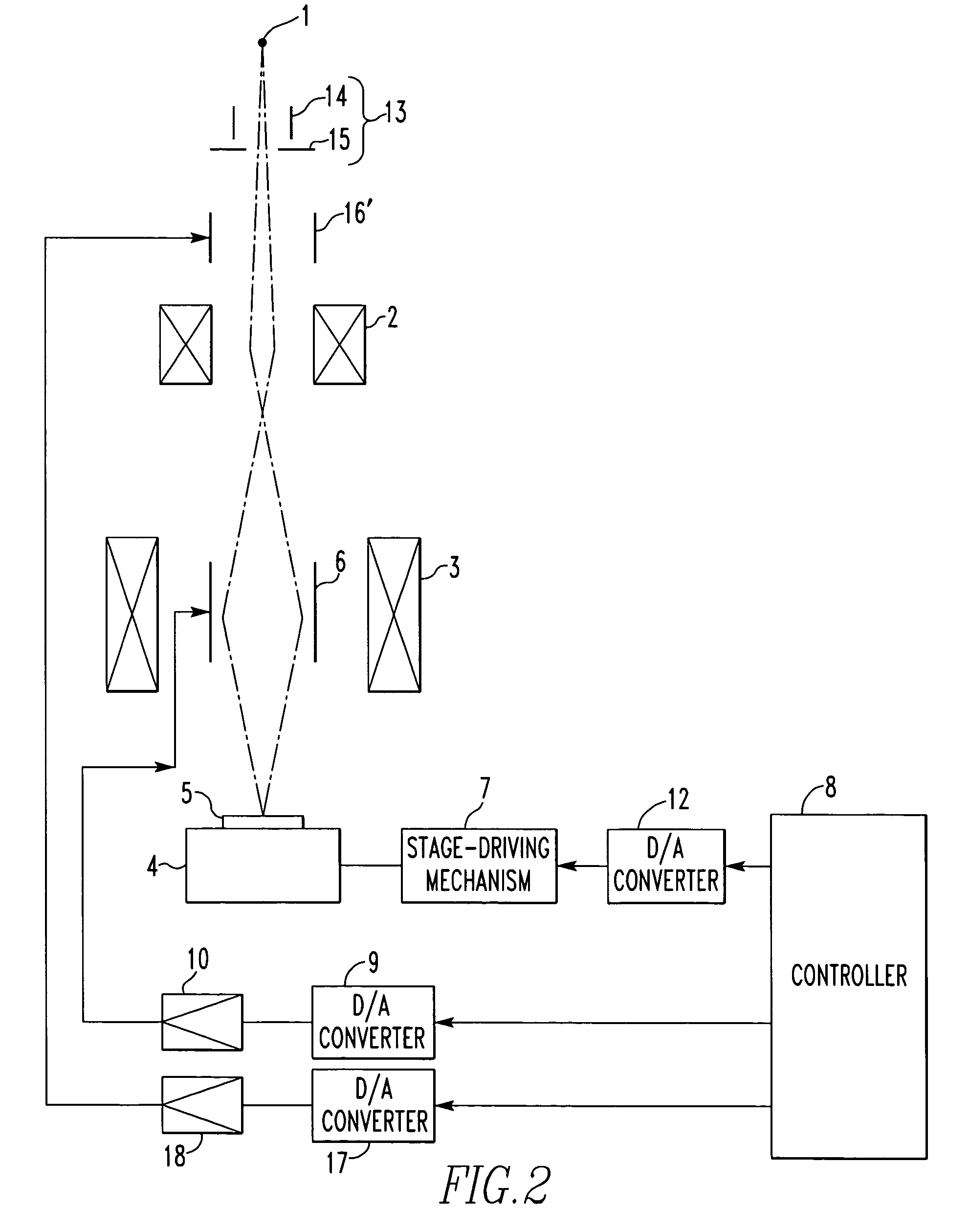
[0027]FIG. 2 schematically shows a charged-particle beam instrument according to one embodiment of the present invention. Note that like components are indicated by like reference numerals in both FIGS. 1 and 2.

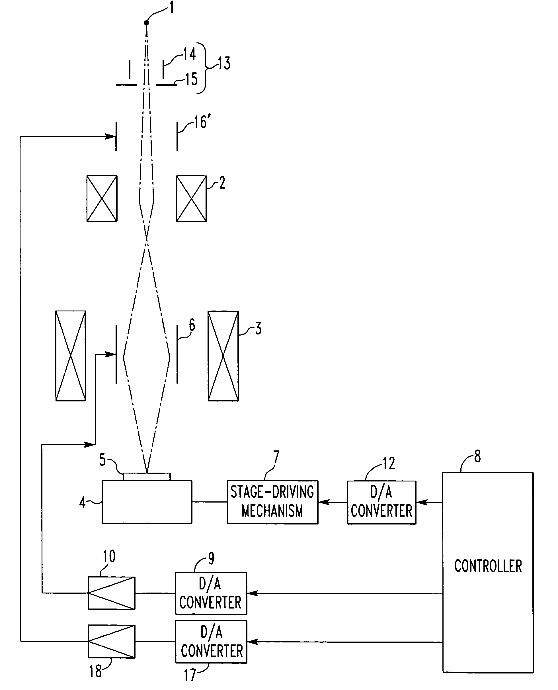
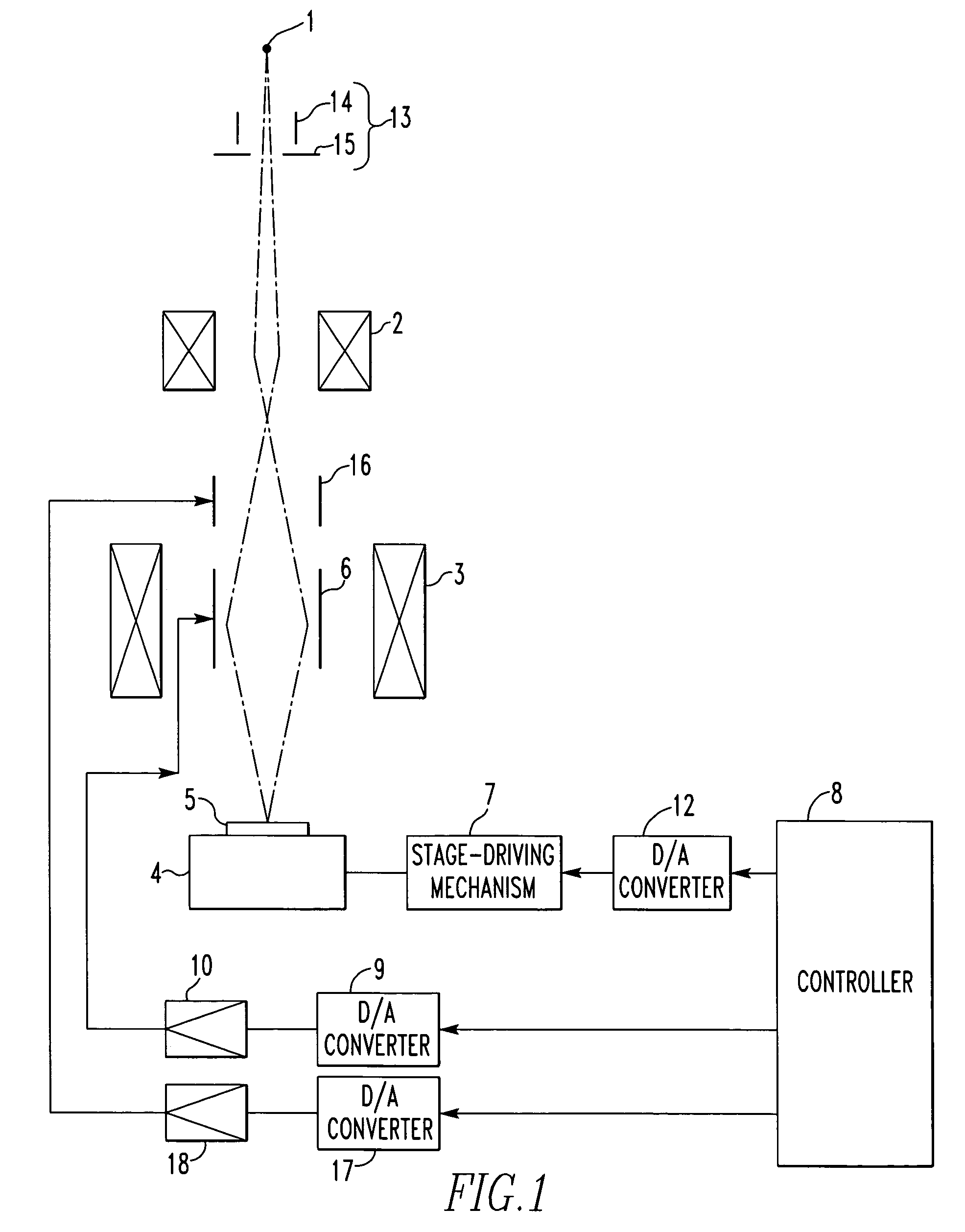
[0028]The charged-particle beam instrument shown in FIG. 2 is similar to the charged-particle beam instrument already described in connection with FIG. 1 except that the second deflector 16′ is placed ahead of the demagnifying lens 2 (between the electron source 1 and the demagnifying lens 2).

[0029]In this structure, if the tilt of the trajectory of the electron beam deflected by the second deflector 16′ is increased by the use of the focusing action of the demagnifying lens 2, the deviation...


PUM


Abstract

A charged-particle beam instrument is offered which can cancel out deflection aberrations arising from a first deflector or oblique incidence on the surface of a workpiece without (i) increasing the electrode length, (ii) reducing the inside diameter of the electrode, or (iii) increasing the deflection voltage too much. The instrument has an electron source for producing an electron beam, a demagnifying lens for condensing the beam, an objective lens for focusing the condensed beam onto the surface of the workpiece, the first deflector located behind the demagnifying lens, and a second deflector located ahead of the demagnifying lens. The first deflector determines the beam position on the surface of the workpiece. The second deflector cancels out deflection aberrations arising from the first deflector.

Description

BACKGROUND OF THE INVENTION[0001]1. Field of the Invention[0002]The present invention relates to a charged-particle beam instrument having a plurality of deflectors cooperating to cancel out their mutual deflection aberrations or oblique incidence.[0003]2. Description of Related Art[0004]In recent years, electron beam lithographic systems have become indispensable for manufacture of semiconductor devices.[0005]FIG. 1 schematically shows one example of such an electron beam lithographic system. The system has an electron source 1 (such as a crossover point in an electron gun, an aperture irradiated with an electron beam and used to shape the cross section of the beam, or an image of the crossover point or the shaping aperture), a demagnifying lens 2 for forming an image of the electron source, and an objective lens 3 for focusing the image formed by the demagnifying lens 2 onto a workpiece 5 placed on a stage 4.[0006]A deflector 6 is used such that an electron beam hits a position on...

Claims


Application Information

Patent Timeline
Patent Type & Authority Patents(United States)
IPC IPC(8): H01J1/50
CPCH01J37/147H01J37/153H01J2237/1534H01J2237/28
Inventor GOTO, KAZUYA
Owner JEOL LTD
Why Eureka
Try Eureka