Scroll machine

a compressor and cranking technology, applied in the direction of machines/engines, functional valve types, liquid fuel engines, etc., can solve the problems of unwanted noise and potential harm to compressor components, and achieve the effect of minimizing the amount of reverse rotation and minimizing the volume of compressed gas

Active Publication Date: 2006-10-19
COPELAND LP
View PDF29 Cites 45 Cited by
  • Summary
  • Abstract
  • Description
  • Claims
  • Application Information

AI Technical Summary

Benefits of technology

[0005] One method of minimizing the amount of reverse rotation is to minimize the volume of compressed gas which will move between the scroll wraps at shutdown. The present invention provides a discharge valve that is designed to be fast acting in closing the discharge port upon shutdown of the compressor.
[0006] A discharge valve, according to the principles of the present invention, includes a valve seat having a seat surface facing downstream of a discharge passage of the scroll compressor. A valve member is provided having a body portion for engaging the seat surface of the valve seat for closing the discharge passage. The valve member includes a guide portion extending axially from the body portion. A retainer is slidably engaged with the guide portion of the valve member and includes at least one passage communicati...

Problems solved by technology

This is undesirable, and results in unwanted n...

Method used


Image

  • Scroll machine
  • Scroll machine
  • Scroll machine

Examples


Embodiment Construction

[0030] The following description of the preferred embodiments is merely exemplary in nature and is in no way intended to limit the invention, its application, or uses.

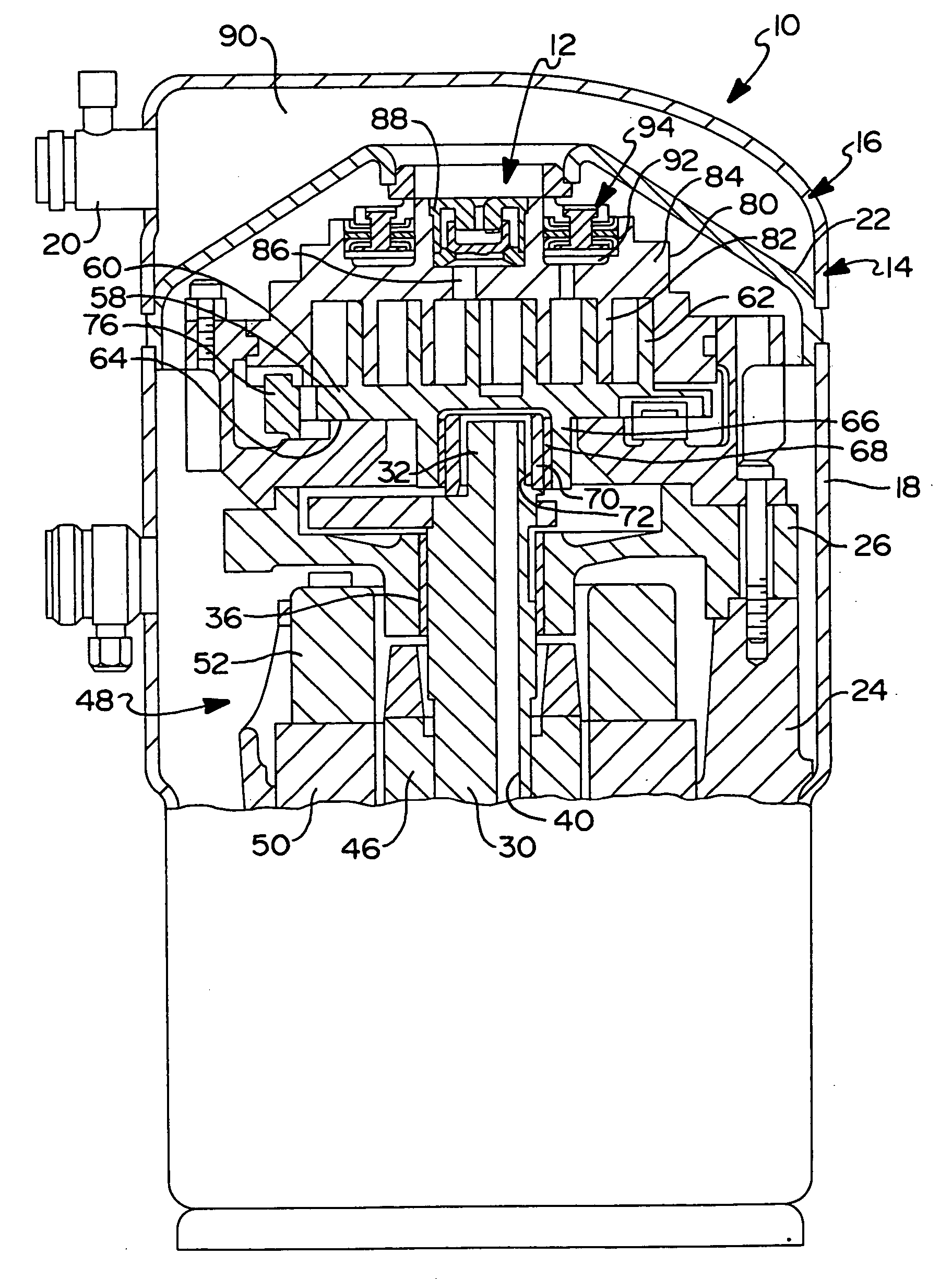
[0031] At the outset, it is noted that the herein described compressor embodiments are the subject of commonly assigned U.S. Patent No. 6,139,291 to Perezovchikov, the disclosure of which is incorporated herein by reference. Referring now to the drawings in which like reference numerals designate like or corresponding parts throughout the several views, there is shown in FIG. 1 a scroll compressor 10 that incorporates a discharge valve assembly 12 in accordance with the present invention. Compressor 10 comprises a generally cylindrical hermetic shell 14 having welded at the upper end thereof a cap 16 and at the lower end thereof a base 18. Cap 16 is provided with a refrigerant discharge fitting 20. Other major elements affixed to shell 14 include a transversely extending partition or muffler plate 22 which is welded t...


PUM


Abstract

A discharge valve assembly is provided for preventing reverse rotation of a scroll compressor. The discharge valve assembly includes a cup-shaped valve member slidably engaged with a central post of a retainer member. The cup-shaped valve member includes notches in communication between the central post of the retainer and the sidewalls of the cup-shaped valve member.

Description

FIELD OF THE INVENTION [0001] The present invention relates to scroll compressors, and more particularly, to discharge valves for preventing reverse rotation of a scroll compressor at shutdown. BACKGROUND AND SUMMARY OF THE INVENTION [0002] Scroll compressors have become widely utilized in many refrigerant compression applications. Scroll compressors are relatively efficient, and are being utilized in more and more applications. In a typical scroll compressor, the compression chambers are defined by two generally spiral wraps. The spiral wraps are formed on individual scroll members, and extend from a base plate. The spiral wraps interfit to define compression chambers. One of the spiral wraps is driven to orbit relative to the other, and the size of the compression chambers changes to compress the entrapped refrigerant. [0003] As the compression chamber nears the end of its cycle, the entrapped gas is exposed to a discharge port. The entrapped gas leaves the discharge port and move...

Claims


Application Information

Patent Timeline
IPC IPC(8): F04C2/00F01C1/02F04C18/00F01C1/063
CPCF04C18/0215F04C29/126F04C28/28Y10T137/7852Y10T137/7851F04C18/02F04C2/02
Inventor BONEAR, RONPEREVOZCHIKOV, MICHAELIGNATIEV, KIRILL
Owner COPELAND LP
Why Eureka
Try Eureka