Compression molding machine

a molding machine and compression molding technology, applied in dough shaping, baking, food shaping and other directions, can solve the problems that the roller-type machine also requires a substantial amount of valuable floor space, and achieve the effects of reducing maintenance requirements and the amount of energy needed to operate, reducing the force applied, and achieving substantial commercial acceptance and success

Inactive Publication Date: 2006-10-19
SACMI COOP MECCANICI IMOLA S C R L
View PDF20 Cites 21 Cited by
  • Summary
  • Abstract
  • Description
  • Claims
  • Application Information

AI Technical Summary

Benefits of technology

[0003] Although vertical axis carousel-type machines of the noted type have enjoyed substantial commercial acceptance and success, innovation remains desirable. In particular, in vertical axis carousel-type machines, the mold forces and the weight of the rotating equipment are parallel to the vertical axis of rotation, creating a bending moment with respect to the axis of rotation and the bearings and shaft that support the carousel. Carousel-type machines also require a substantial amount of valuable floor space in a manufacturing facility. It is a general object of the present disclosure, in accordance with one aspect of the disclosure, to provide a method and apparatus for compression molding plastic articles, such as plastic closures and plastic liners within closure shells, which reduce the forces applied to the support frame and bearings, reduce maintenance requirements and the amount of energy needed to operate the machine, and / or reduce the amount of floor space required per machine.

Problems solved by technology

Carousel-type machines also require a substantial amount of valuable floor space in a manufacturing facility.
However, movement of the female mold segment also could impart rotary motion to the stripper sleeve to unthread a molded closure from the mold core, for example.

Method used


Image

  • Compression molding machine
  • Compression molding machine
  • Compression molding machine

Examples


Embodiment Construction

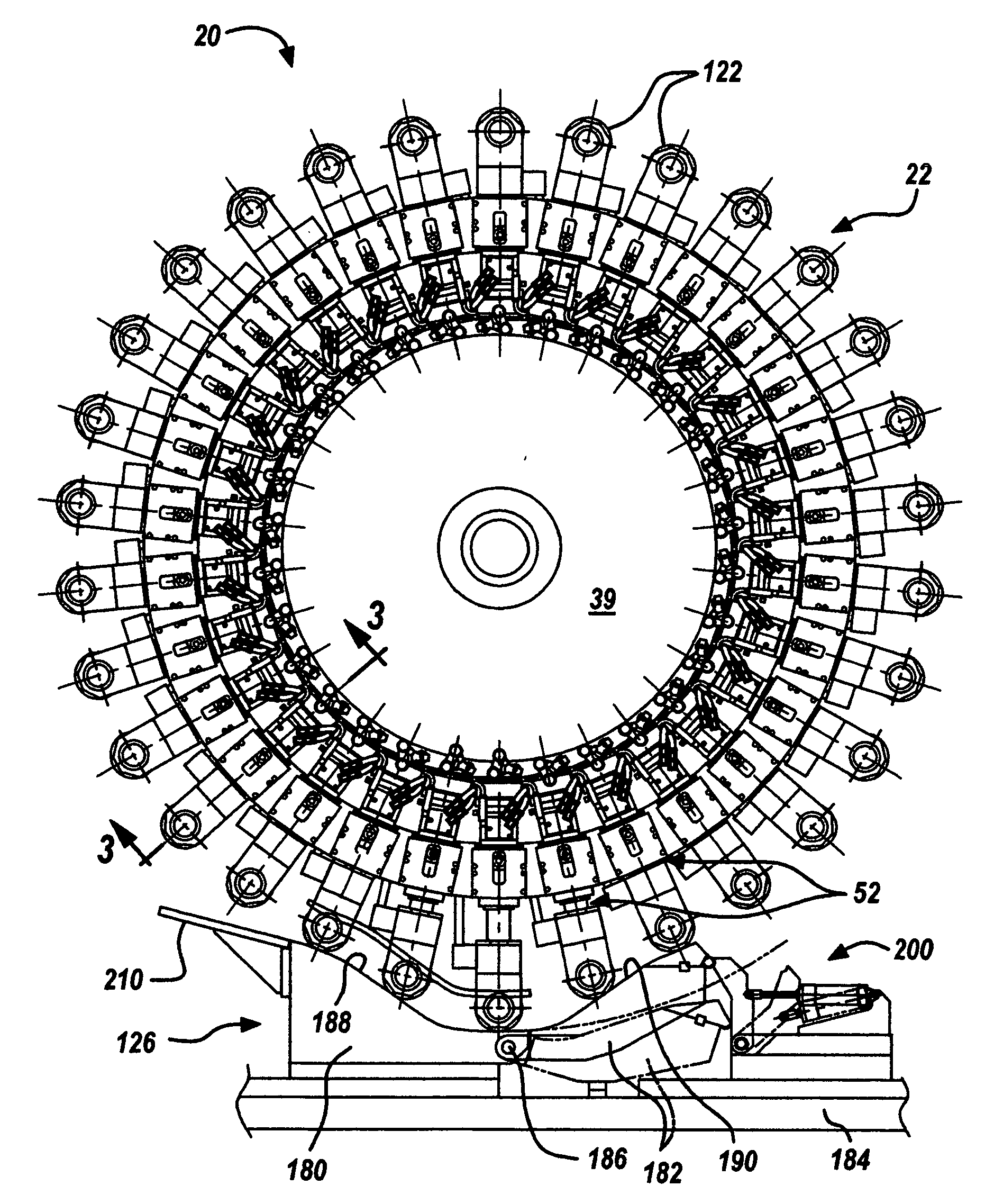
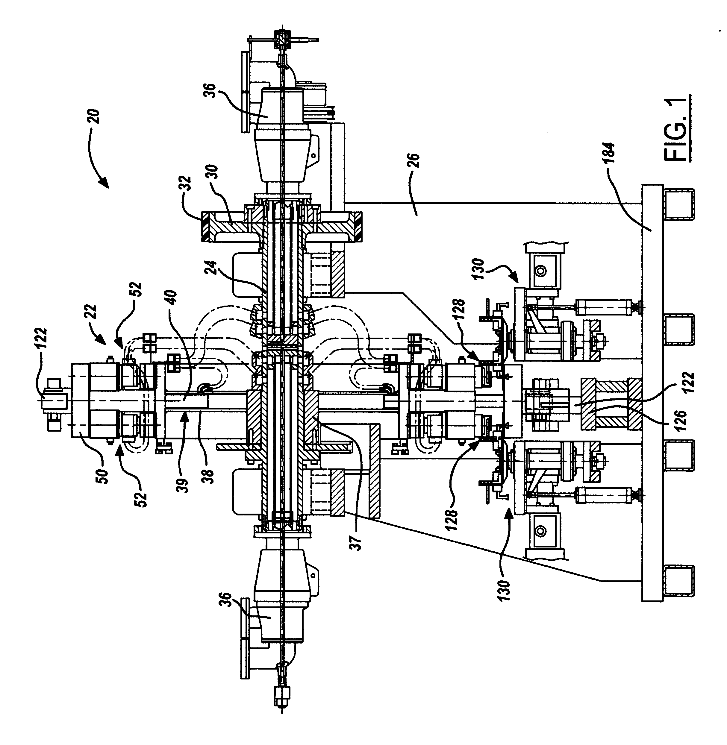
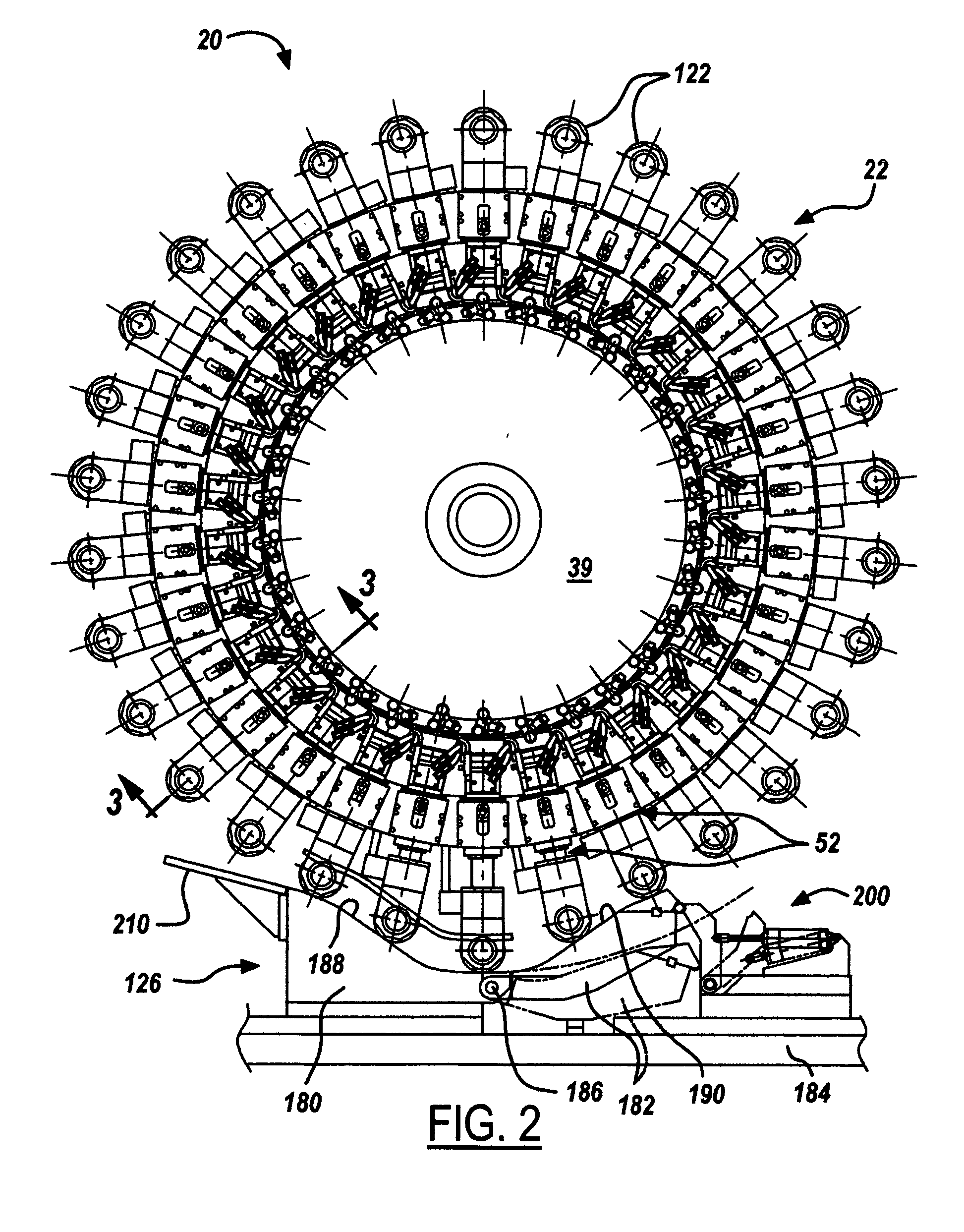
[0035]FIGS. 1-2 illustrate one presently preferred embodiment of the disclosure in the form of a machine 20 for compression molding plastic closure shells. Machine 20 includes a wheel 22 mounted on a shaft 24 between spaced supports 26. Shaft 24 is coupled by a pulley 30 and a belt 32 to a motor 36 (FIG. 7) for rotating shaft 24 and wheel 22 around a horizontal axis. Wheel 22 includes a hub 37 (which may be part of shaft 24) and a support 39 extending radially from hub 37. Support 39 may comprise a disk or the like, or may be in the form of a plurality of angularly spaced radially extending support spokes 38. Each support spoke 38 is hollow at its outer end. A rod 40 is slidably supported by sleeve bearings 42 (FIGS. 3B-3C) within the hollow outer end of each spoke 38. A crossbar 50 is coupled to the end of each rod 40, so that the combination of rod 40 and bar 50 is generally T-shaped as viewed from the tangential direction in FIG. 1. A pair of radially spaced external supports 44,...


PUM

PropertyMeasurementUnit
forceaaaaaaaaaa
weightaaaaaaaaaa
forcesaaaaaaaaaa

Abstract

A compression molding machine includes a wheel mounted for rotation around a horizontal axis and a plurality of angularly spaced molds disposed around the wheel. Each of the molds includes a first mold segment and a second mold segment disposed radially outwardly of the first mold segment. Each of the second mold segments is movable radially with respect to the associated first mold segment between a radially inner closed position with the first mold segment for compression molding a plastic article, and a radially outer open position spaced from the associated first mold segment for removing a molded article from the mold and placing a mold charge into the mold.

Description

[0001] The present disclosure is directed to a machine for molding plastic articles, such as closure shells or sealing liners within closure shells. BACKGROUND AND SUMMARY OF THE INVENTIONS [0002] Machines for compression molding closure shells, or compression molding sealing liners within closure shells, typically include a turret or carousel that rotates around a vertical axis. A plurality of molds are provided around the periphery of the carousel, in the form of male and female mold sections that are aligned along vertical axes parallel to the axis of rotation. Cams drive one or both of the mold sections of each pair between an open position, in which a molded part is stripped from the male mold section and a charge of plastic material is placed in the female mold section, and a closed position in which the male and female mold sections are brought together to compression mold the shell or liner. In a liner machine, premade shells are placed in a nest when the mold sections are o...

Claims


Application Information

Patent Timeline
Patent Type & Authority Applications(United States)
IPC IPC(8): B29C51/00
CPCB29C43/08B29C2043/3684B29C2043/3288
Inventor MATTICE, DANIEL L.ROTE, B. JACK
Owner SACMI COOP MECCANICI IMOLA S C R L
Why Eureka
Try Eureka