Power loading method and apparatus for throughput enhancement in MIMO systems

Inactive Publication Date: 2006-10-19
SAMSUNG ELECTRONICS CO LTD
View PDF5 Cites 22 Cited by
  • Summary
  • Abstract
  • Description
  • Claims
  • Application Information

AI Technical Summary

Benefits of technology

[0010] As such, the controller essentially optimizes transmission power distribution per channel for enhanced

Problems solved by technology

Under this consideration, conventional methods such as the “water-filling” algorithm for power loading (power c

Method used


Image

  • Power loading method and apparatus for throughput enhancement in MIMO systems
  • Power loading method and apparatus for throughput enhancement in MIMO systems
  • Power loading method and apparatus for throughput enhancement in MIMO systems

Examples


Embodiment Construction

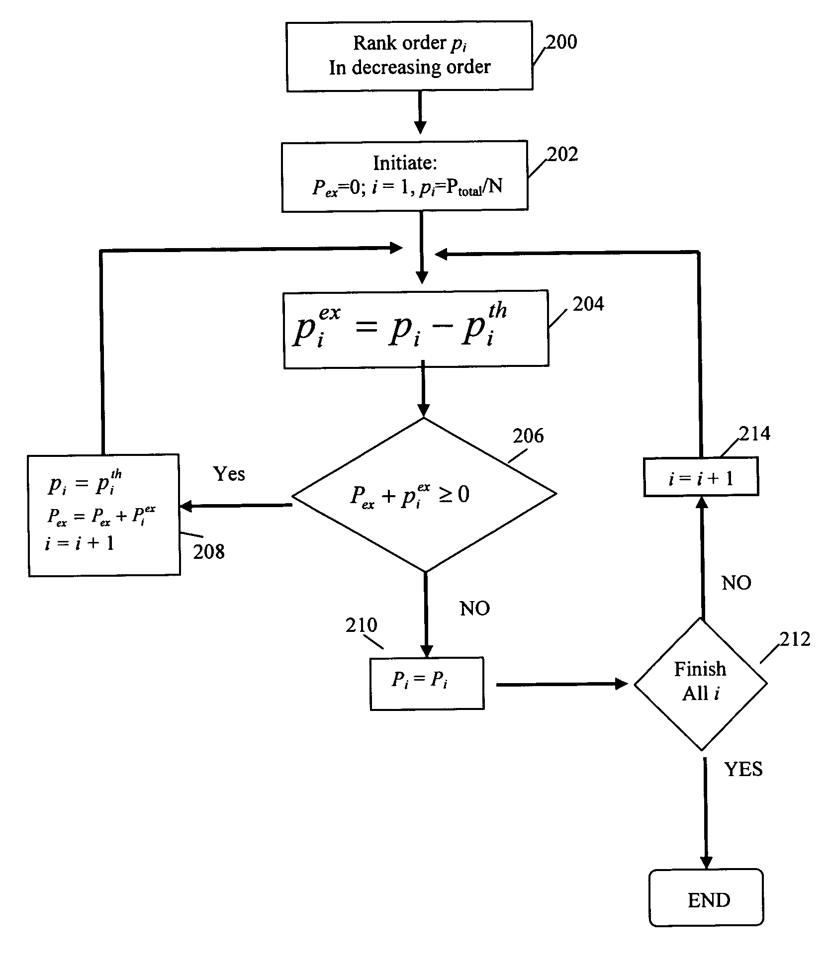
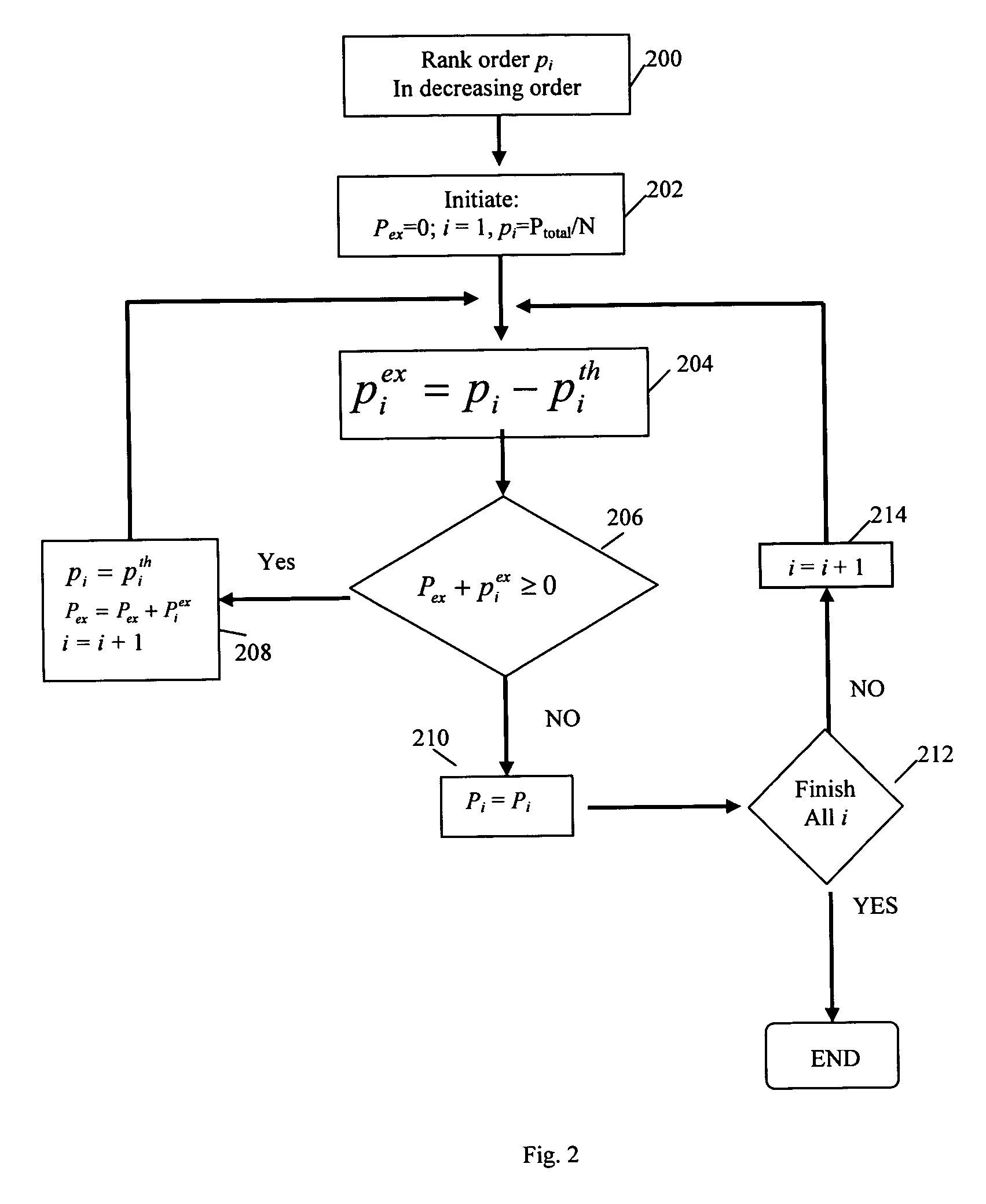
[0016] In a MIMO system, transmission power has to be properly distributed over the antennas to maximize the capacity. For an unknown channel, uniform power distribution over the antennas can be applied. For a known channel, optimum power distribution using the “water-filling” technique can be utilized, wherein the “water-filling” algorithm can be derived after converting the MIMO channel into a set of parallel channels using a singular value decomposition (SVD) of the channel matrix.

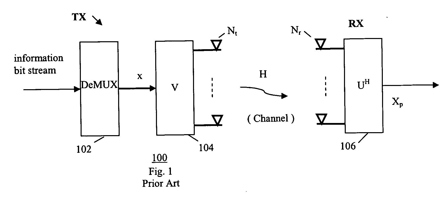
[0017] Referring to the example function block diagram in FIG. 1, a conventional SVD-type MIMO system 100 includes a transmitter TX and a receiver RX, providing a beamforming technique used in closed-loop MIMO systems. Using SVD, a MIMO channel can be decomposed into several independent channels for data transmission, and therefore, there are no interferences between different data streams at the receiver.

[0018] For the MIMO system 100 having a channel H, and Nt transmission antennas and Nr receiving ...


PUM


Abstract

An apparatus and method for closed-loop signaling over multiple channels in a telecommunication system. Channel condition for each channel is obtained, and transmission power loading per channel is determined according to channel condition. The information bit streams is transmitted via the multiple channels over a plurality of transmitter antennas according to the power loading per channel.

Description

FIELD OF THE INVENTION [0001] The present invention relates generally to data communication, and more particularly, to data communication in multi-channel communication system such as multiple-input multiple-output (MIMO) systems. BACKGROUND OF THE INVENTION [0002] A multiple-input-multiple-output (MIMO) communication system employs multiple transmit antennas in a transmitter and multiple receive antennas in a receiver for data transmission. A MIMO channel formed by the transmit and receive antennas may be decomposed into independent channels, wherein each channel is a spatial sub-channel (or a transmission channel) of the MIMO channel and corresponds to a dimension. The MIMO system can provide improved performance (e.g., increased transmission capacity) if the additional dimensionalities created by the multiple transmit and receive antennas are utilized. [0003] MIMO techniques are adopted in wireless standards, such as 3 GPP, for high data rate services. In a wireless MIMO system, ...

Claims


Application Information

Patent Timeline
IPC IPC(8): H04B7/00H04Q7/20H04W48/12H04W52/00H04W52/42
CPCH04B7/04H04B7/0626H04W52/42H04L1/0618H04W48/12H04B7/0697
Inventor NGO, CHIU
Owner SAMSUNG ELECTRONICS CO LTD
Why Eureka
Try Eureka