Infinity shower pan

a shower pan and infinity technology, applied in the field of shower pans, can solve the problems of not knowing how the surrounding area will be finished, material corrosion or harmful to the material, scratching, discoloration, etc., and achieve the effect of reducing the air space, simplifying the finishing of the shower enclosure, and reducing the cos

Inactive Publication Date: 2006-10-26
POLIMENO JOHN
View PDF5 Cites 61 Cited by
  • Summary
  • Abstract
  • Description
  • Claims
  • Application Information

AI Technical Summary

Benefits of technology

[0009] The final slab floor member in the final installation is not glued to the support structure of the shower pan, but rather rests on the support structure and is held in place by gravity. In some embodiments, the slab floor member has an indent that engages a portion of the support structure that extends up past the plane of the support plane so that once the indent-in the slab floor member is put in place over the portion, the slab floor member is thereafter held in place and prevented from slipping. Other mechanisms for preventing excessive movement of the slab floor member are employed in other embodiments.
[0011] Multiple different shower pan configurations are possible that both drain to a drain orifice and also include the novel support structure. In one example, the support structure contacts a large proportion of the underside planar surface of the slab floor member, thereby minimizing the air space underneath the slab floor member. A peripheral drain trough formed in the upper surface of the shower pan catches water that falls off the peripheral edges of the slab floor member. The peripheral drain trough conducts this water into a drain channel that extends to the drain orifice located under the slab floor member in the center of the shower pan. A removable screen or grill is provided to filter water as it passes from the peripheral drain trough into the drain channel.
[0012] In one novel aspect, a novel shower pan and a novel threshold extension portion is available for retail purchase. A wide selection of cladding kits are also made available for retail purchase. Each cladding kit includes a set of precut cladding sheets for cladding the walls of the shower enclosure, a set of precut cladding pieces for cladding the threshold portion, and a precut slab floor member made of the same cladding material. An individual can purchase the shower pan and threshold extension portion at a retail store, and install the shower pan at the rough-in stage of construction without having to decide which cladding material will later be used to finish the installation. Later, when the shower enclosure is to be finished, the individual consults the large selection of available cladding kits and selects a cladding kit that has a desired finishing material and look. Because the cladding sheets and pieces in each kit are precut, the finishing of the shower enclosure is simplified and made less expensive. The precut cladding pieces can be mass-produced, thereby reducing per unit cost and decreasing the cost of the cladding kits.

Problems solved by technology

Materials that are corrosive or harmful to the material of which the shower pan is made may also be spilled or dumped into the shower pan.
The unfortunate result is that the smooth surface of the shower pan is covered in difficult to remove materials, is scratched, is discolored, or is otherwise damaged.
Another problem is that at the rough-in stage in the construction process when the shower pan is installed, it may not yet be known how the surrounding area will be finished.
Unfortunately, when the shower pan is installed at the rough-in stage of construction, the color and style of the shower pan has to be decided before these other design decisions have been made.
Although synthetic cast shower pans function well, the look and feel of the artificial cast material may be less aesthetically pleasing to some than other finishing materials.
The labor associated with this cladding operation can entail substantial cost.
Unfortunately, getting the pieces to align in this way is often difficult and expensive.

Method used


Image

  • Infinity shower pan
  • Infinity shower pan
  • Infinity shower pan

Examples


Embodiment Construction

[0027] Reference will now be made in detail to some embodiments of the invention, examples of which are illustrated in the accompanying drawings.

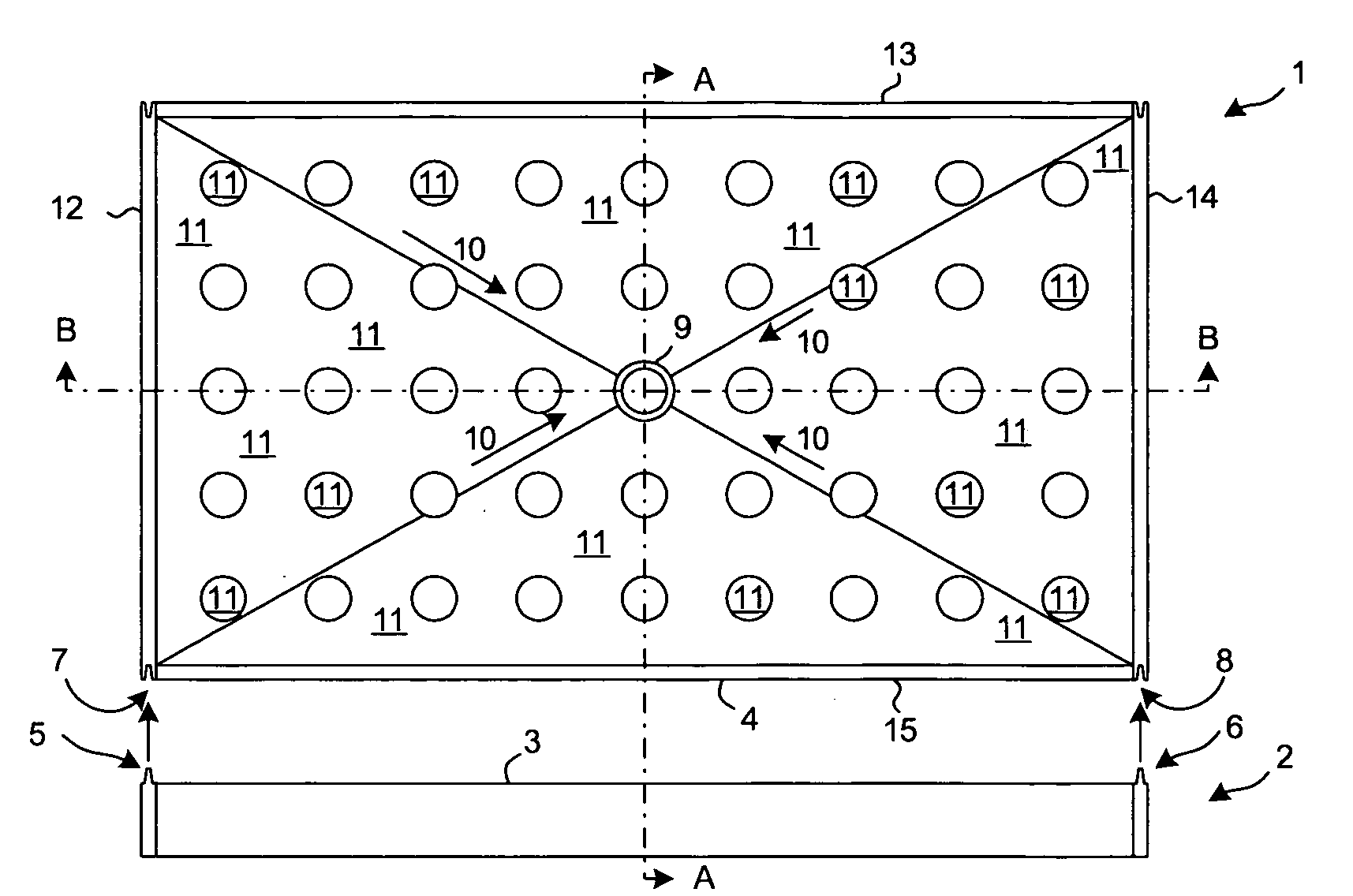
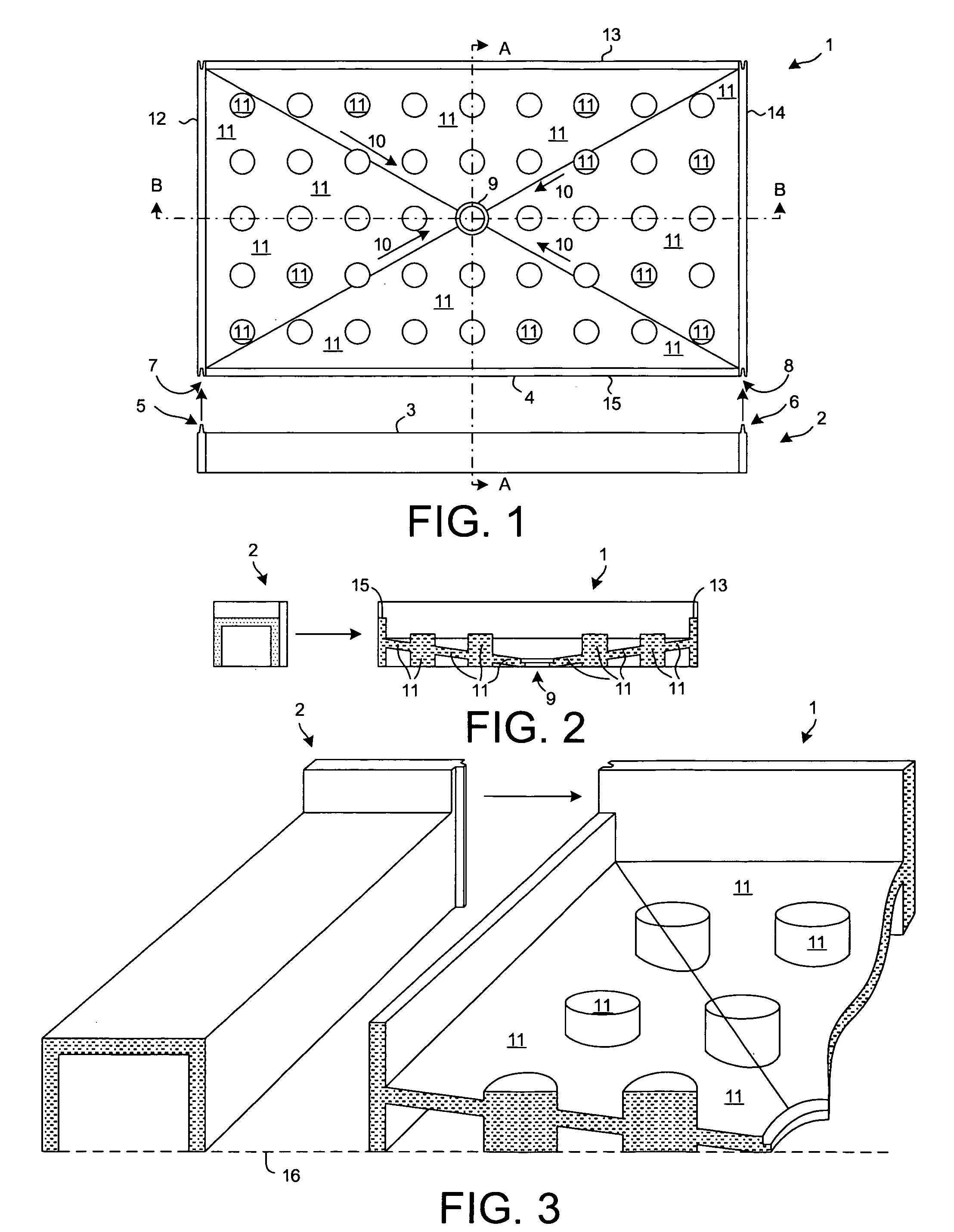
[0028]FIG. 1 is a simplified top-down diagram of a novel shower pan 1 and threshold extension portion 2. Both the shower pan and the threshold extension portion are unitary articles. Each article may, for example, be a cast cured resin article.

[0029] In a first example, each of the two articles is a cast piece of cultured marble. To make one of the articles, a liquid polyester resin material is used as a starting ingredient. An effective amount of a catalyst such as an organic peroxide is added to the liquid polyester material and the two materials are mixed. Calcium carbonate, in granular and / or powder form, is then added. The calcium carbonate acts as a filler in the finished cultured marble material. Pigment can be added at this stage if desired. The mixture has a soupy consistency much like the consistency of runny cookie dough. The s...


PUM


Abstract

A shower pan includes a draining base portion that drains to an orifice. The draining base portion includes a support structure for supporting a slab floor member (for example, a single piece of granite, marble, or engineered stone) above the orifice such that a planar upper surface of the floor member has a slight tilt. The pan is installed such that the tilt is toward a shower head. The shower enclosure is finished by cladding the enclosure walls with a finishing material (for example, granite, marble or engineered stone) such that the finishing material extends down into the pan. The floor member is placed on the support structure such that water from the shower head that falls on the floor member runs off one or more edges of the floor member and is conducted to the orifice under the floor member by a draining portion of the draining base portion.

Description

TECHNICAL FIELD [0001] The present invention relates to shower pans. BACKGROUND INFORMATION [0002] Cast cultured marble shower pans are typically installed at the rough-in stage of construction. Because the shower pan is installed so early in the construction process, construction workers perform their trades in the area around the shower pan after the shower pan has already been installed. The construction workers may, for example, drop nails, screws and other building materials in the shower pan, and then walk into the shower, on the shower pan, and over the nails and other debris. Materials that are corrosive or harmful to the material of which the shower pan is made may also be spilled or dumped into the shower pan. The unfortunate result is that the smooth surface of the shower pan is covered in difficult to remove materials, is scratched, is discolored, or is otherwise damaged. A solution is desired. [0003] Another problem is that at the rough-in stage in the construction proc...

Claims


Application Information

Patent Timeline
Patent Type & Authority Applications(United States)
IPC IPC(8): A47K3/36A47K3/34
CPCA47K3/40
Inventor POLIMENO, JOHN
Owner POLIMENO JOHN
Why Eureka
Try Eureka