
Combination lift and anchor connector for fabricated wall and floor panels

a technology of fabricated wall and floor panels and anchor connectors, which is applied in the field of low density prefabricated concrete building panels, can solve the problems of increasing the odds of cracking or otherwise changing the floor panel, the method of interconnecting the wall panel with the floor panel is slightly more labor-intensive, etc., and achieves the effect of simple and cost-effective installation

Inactive Publication Date: 2006-10-26
OLDCASTLE PRECAST
View PDF99 Cites 23 Cited by
  • Summary
  • Abstract
  • Description
  • Claims
  • Application Information

AI Technical Summary

Benefits of technology

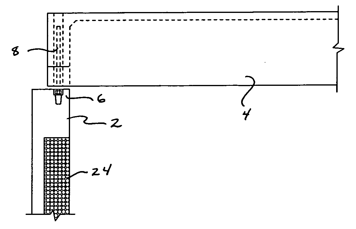
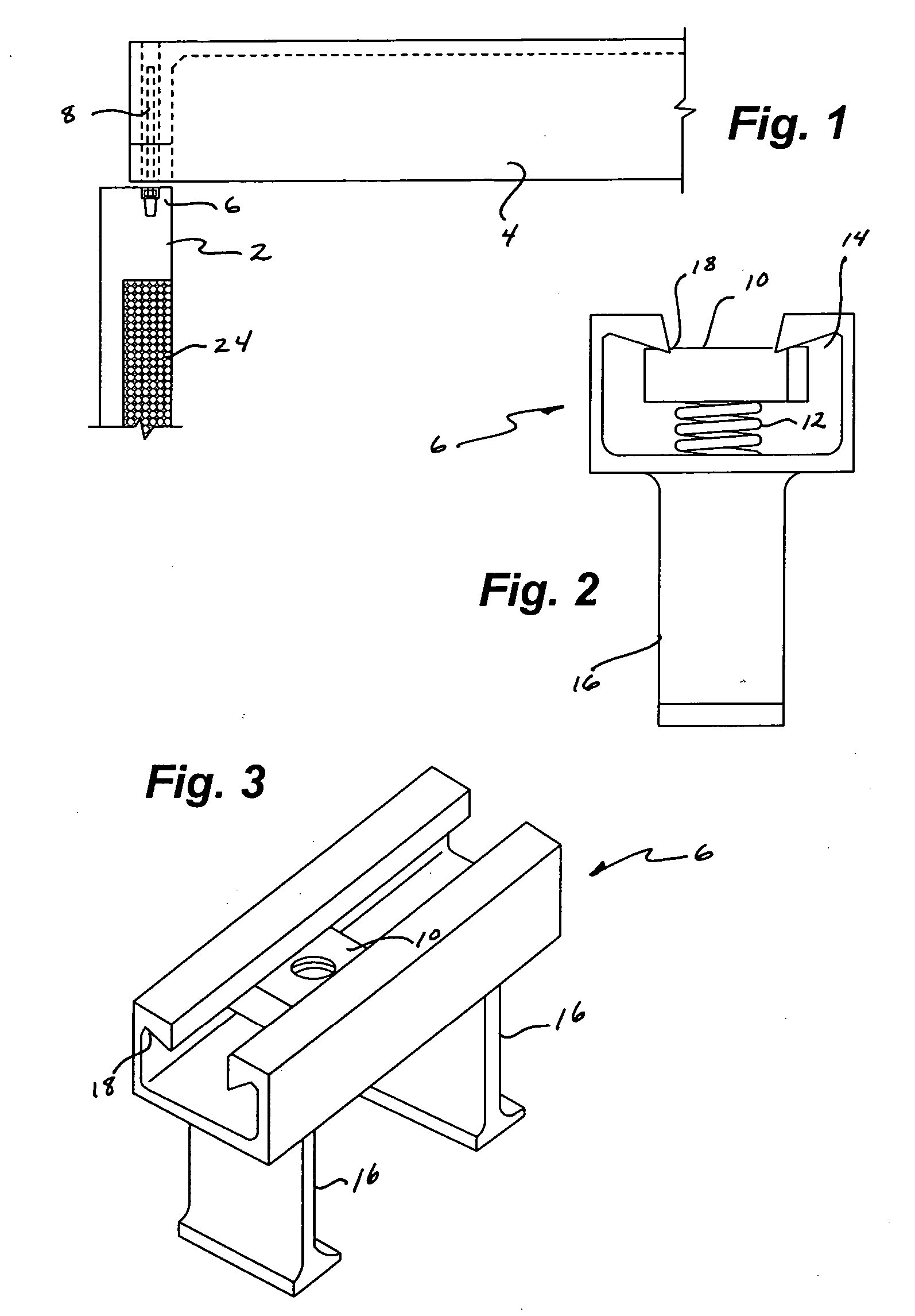
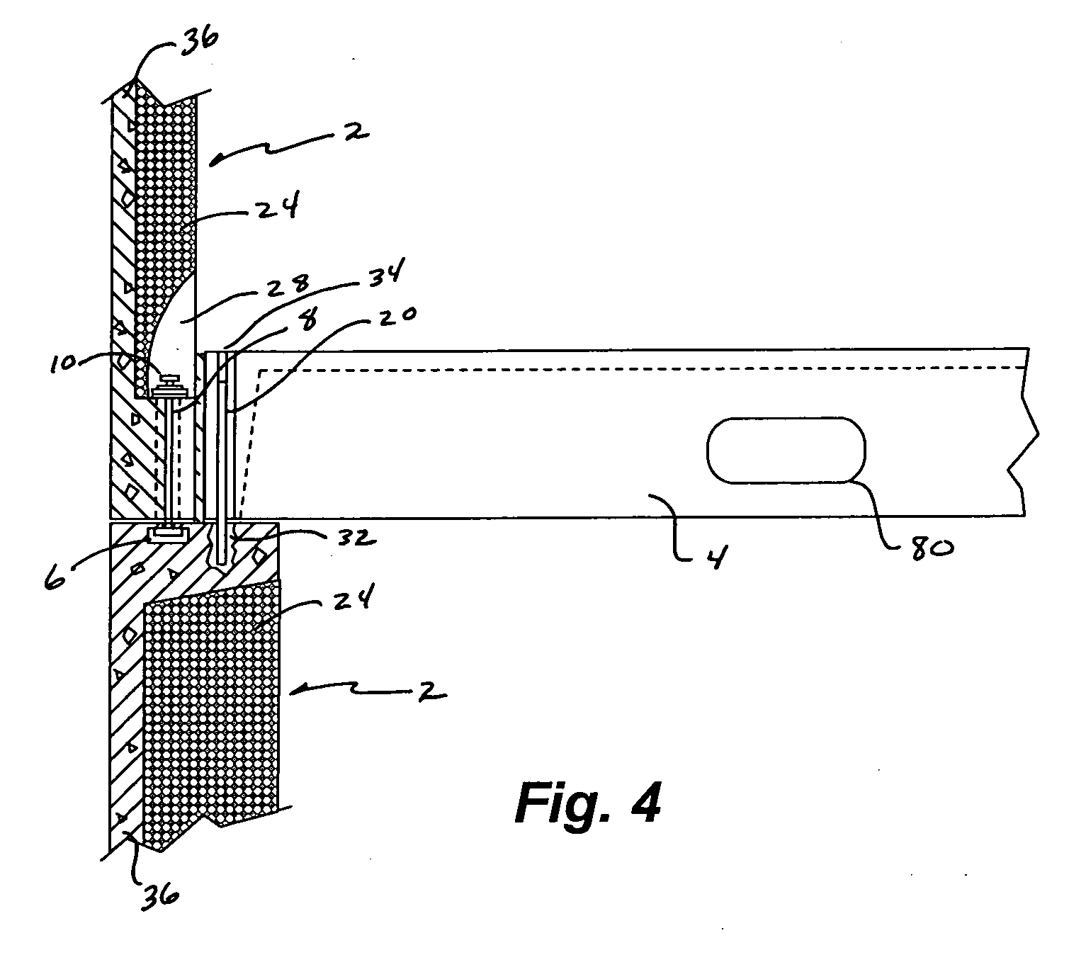
[0011] As briefly mentioned above, the adjustable connector in one embodiment includes a captive nut. Once the floor panel is placed over the wall panel, with the aperture of the floor panel aligned with the adjustable connector embedded in the wall panel, a threaded rod is placed through the aperture. A nut is then threaded onto the rod and secured, thus substantially fixing the fabricated floor and wall panels together. Next, a combination of sand or other granular material and / or epoxy may be added to fill the aperture of the floor panel, thereby substantially preventing the infiltration of fluids and further strengthening the interconnection. Furthermore, the granular material has been found to provide increased stability during a seismic disturbance or high winds since rigidity between the floor panel and wall panel is reduced.
[0013] It is yet another aspect of the present invention to provide an interconnecting mechanism that is simplistic and cost effective to install. More specifically, the adjustable connector of one embodiment of the present invention is placed in the wall panel mold prior to the placing of concrete, wherein the connector is embedded adjacent to the upper edge of the finished wall panel. In addition, the lifting tube as previously described above, would be also set in the precast mold of the floor prior to the placement of concrete thus providing a finished product with the steel sheath in its predetermined location.

Problems solved by technology

This method of interconnecting the wall panel to the floor panel is slightly more labor intensive, since the hole must e drilled in the field because the odds of cracking or otherwise changing the floor panel are somewhat increased.

Method used


Image

  • Combination lift and anchor connector for fabricated wall and floor panels
  • Combination lift and anchor connector for fabricated wall and floor panels
  • Combination lift and anchor connector for fabricated wall and floor panels

Examples


Embodiment Construction

[0037] Referring now to FIGS. 1-11, a combination lift and anchor connector for fabricated wall and floor panels is provided herein. More specifically, an apparatus and method for interconnecting a floor panel 4 to a wall panel 2 or two wall panels 2 constructed of precast concrete and other materials is provided. One embodiment of the present invention includes an adjustable interconnection device 6 that includes a slidable captive nut 10 or other mechanism. The adjustable interconnection device 6 is integrated into the concrete wall panel 2 during construction such that it will be located adjacent to an aperture 26 integrated into the floor panel 4 after assembly. Prior to the placement of the floor panel 4 over the wall panel 2, minute changes to the location of the captive nut 10 may be made such that a threaded rod 8 may be placed through the aperture 26 integrated into the floor panel 4 to interconnect with the captive nut 10. Once the threaded rod 8 is secured to the captive ...


PUM


Abstract

An apparatus and method for interconnecting concrete precast floor and wall panels is provided. More specifically, one embodiment of the present invention includes an adjustable connector with a captive nut that is embedded into a wall panel. A floor panel that includes an aperture integrated therethrough is placed adjacent to the adjustable connector wherein the captive nut therein may be positioned in line with the aperture. A threaded rod is then placed through the aperture of the floor panel and a nut is placed thereon thus providing a secure interconnection between the floor panel and the wall panel.

Description

[0001] This application claims the benefit of pending U.S. provisional patent application Ser. No. 60 / 667,590, filed on Apr. 1, 2005, the application being incorporated herein by reference in its entirety.FIELD OF THE INVENTION [0002] The present invention relates to low density prefabricated concrete building panels, and more specifically an apparatus and method for interconnecting prefabricated concrete floor and roof panels to wall panels, and which utilizes a selectively adjustable connector. More specifically, one embodiment of the invention employs an adjustable captive nut in conjunction with a threaded rod to interconnect adjoining floor and wall panels. BACKGROUND OF THE INVENTION [0003] Precast concrete panels are well known in the art and have been used for decades as cost effective building components. More specifically, Precast concrete panels are commonly found in office buildings, parking garages, homes, bridges, etc., and are desirable for their resistance to fire, w...

Claims


Application Information

Patent Timeline
IPC IPC(8): E04B1/00
CPCE04B1/0007E04B1/4107E04B1/04
Inventor MESSENGER, HAROLD G.
Owner OLDCASTLE PRECAST
Learn More