Means for securing the lower end of a wind turbine tower to a foundation

Active Publication Date: 2006-10-26
VALMONT INDUSTIES INC
View PDF7 Cites 64 Cited by
  • Summary
  • Abstract
  • Description
  • Claims
  • Application Information

AI Technical Summary

Benefits of technology

[0013] Still another object of the invention is to provide a means of the type described ab

Problems solved by technology

The fact that the hollow structural member (wind turbine tower) of the co-pending application is not perfectly cylindrical or tubular in shape makes it somewhat difficult to anchor or bolt the lowermost pole section to the foundation.
A fu

Method used


Image

  • Means for securing the lower end of a wind turbine tower to a foundation
  • Means for securing the lower end of a wind turbine tower to a foundation
  • Means for securing the lower end of a wind turbine tower to a foundation

Examples


Embodiment Construction

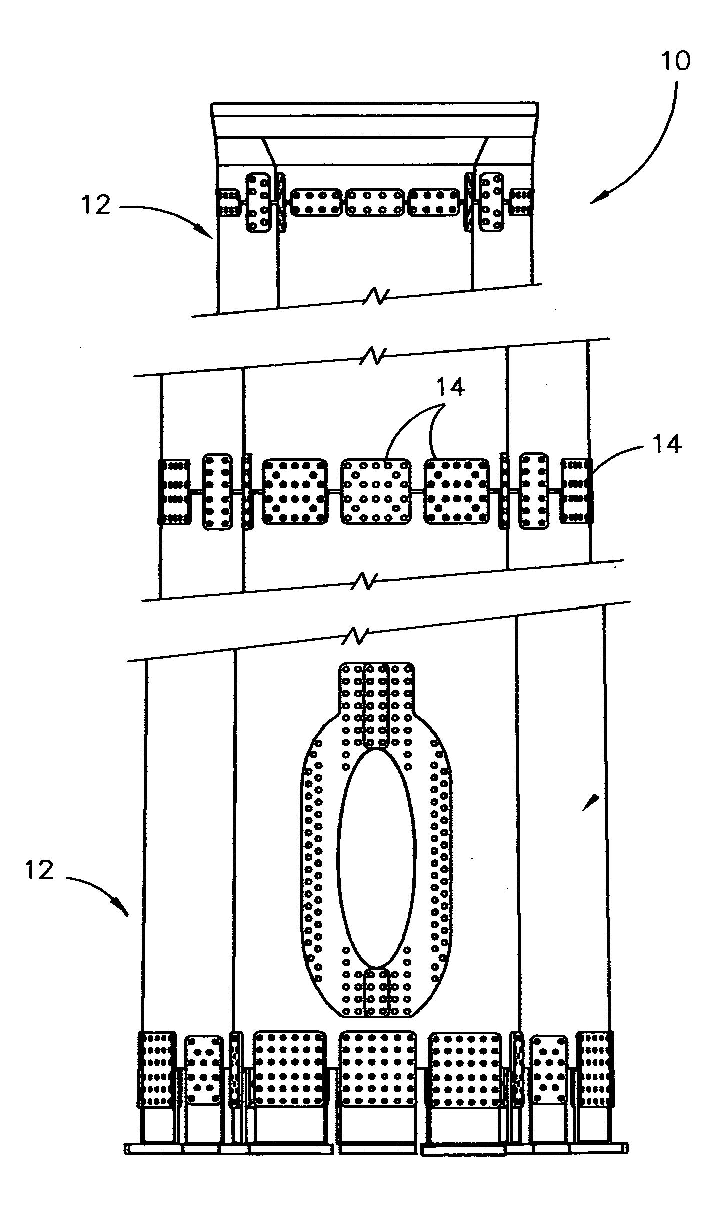
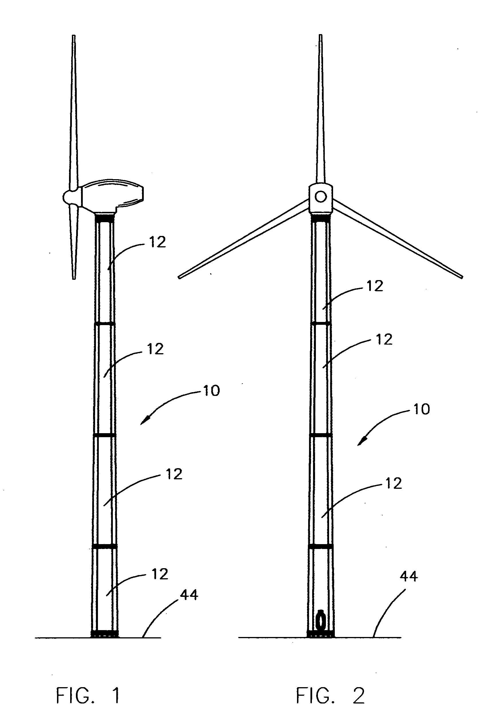
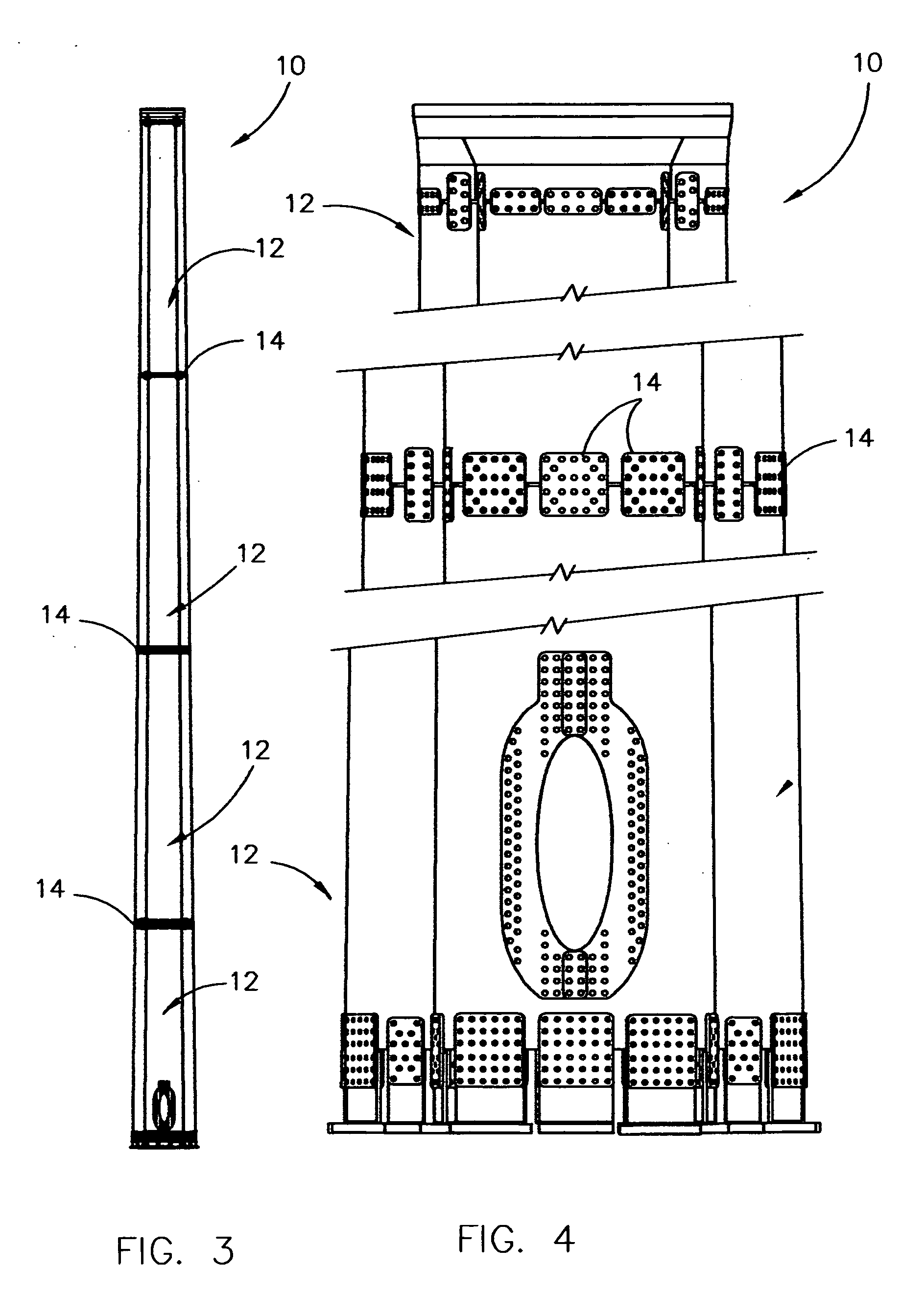
[0024] The numeral 10 refers to a hollow, elongated structural member (wind turbine tower) comprised of a plurality of elongated hollow metal pole sections 12 which are secured together in an end-to-end relationship by splice plate assemblies 14, such as described in assignee's co-pending patent application Ser. No. 10 / 463,155 filed Jun. 17, 2003, entitled “TWO-PLATE SPLICE CONNECTION ASSEMBLY”. Pole sections 12 may be tapered or non-tapered as desired. Each of the pole sections 12 is of the type described in assignee's co-pending application Ser. No. 10 / 797,778 filed Mar. 10, 2004, entitled “HOLLOW STRUCTURAL MEMBER”.

[0025] Each of the pole sections 12 is constructed of a plurality of longitudinally extending peripheral sections 16, preferably four (FIG. 6). Each section 16 is formed or bent from a flat sheet having side edges, an upper edge and a lower edge. If the wind tower is tapered, the width of the upper edge of the sheet will be less than the width of the lower end thereof...


PUM


Abstract

An inverted T-shaped connection member is disclosed for securing the lower end of an upstanding wind turbine tower to a foundation with the tower comprising a plurality of longitudinally extending peripheral sections joined together with each of the peripheral sections being bent along a plurality of longitudinally extending break lines to define a plurality of angled wall sections extending between inwardly extending edge portions with the lower ends of the peripheral sections having bolt openings formed therein. Each of the inverted T-shaped connection members has a generally horizontally disposed base portion and a generally vertically disposed web portion. The base portions of the connection members are secured to the foundation by bolts or the like. The upper ends of the web portions have bolt openings formed therein with the same being secured to the lower end of the tower by means of splice plates.

Description

BACKGROUND OF THE INVENTION [0001] 1. Field of the Invention [0002] This invention relates to a means for securing the lower end of a wind turbine tower to a foundation and more particularly to a means for securing the lower end of a wind turbine tower to a foundation wherein the wind turbine tower is comprised of a plurality of elongated hollow pole sections secured together in an end-to-end relationship with each of the pole sections comprising a plurality of longitudinally extending peripheral sections joined together with each of the peripheral sections being bent along a plurality of longitudinally extending break lines to define a plurality of angled wall sections extending between inwardly extending edge portions. Although the preferred construction of the pole sections is that described above, the wall sections of the peripheral sections could be curved rather than angled. Further, the edge portions of the peripheral sections could extend outwardly, or be in an overlapping o...

Claims


Application Information

Patent Timeline
IPC IPC(8): E02D27/00E04C3/30
CPCE04C3/30Y02E10/728F03D11/04F03D13/20F03D13/22Y02E10/72
Inventor GRUNDMAN, CURTIS M.KOCH, DAN A.
Owner VALMONT INDUSTIES INC
Why Eureka
Try Eureka