High Efficiency Fluid Heat Exchanger and Method of Manufacture

a heat exchanger and high-efficiency technology, applied in the field of heat exchangers, can solve the problems of difficult and expensive manufacturing of such configurations, high manufacturing cost, and high cost of prior-art heat exchangers, and achieve good thermally conductive bond, small heat exchanger, and large surface area

Inactive Publication Date: 2006-10-26
FERROTEC USA CORP
View PDF14 Cites 58 Cited by
  • Summary
  • Abstract
  • Description
  • Claims
  • Application Information

AI Technical Summary

Benefits of technology

[0015] The fin members are connected to the base, preferably by brazing, in order to provide a good thermally conductive bond between the fin members and the base. The fin members are arranged so that the passageways are in an alternating configuration so that the flow of fluid through the housing is continuously altered resulting in a relatively large surface area within a relatively small heat exchanger. The alternating configuration of the fin members causes the fluid to turbulently flow through the heat exchanger while exposing a greater portion of the fluid volume to the thermally conductive fin members leading to a more efficient heating or cooling effect.
[0016] The cover is sealingly connected to the base, preferably by brazing, and the desired fluid inlet and fluid outlet fittings are attached to the housing so that the fluid inlet and fluid outlet are positioned relative to the fin members to cause the flow of the heat exchange fluid to flow through and across each fin members in sequential order. Because the present invention can be assembled using a minimum number of different components, the present invention provides a heat exchanger that is inexpensive to make, easy to assembly, easy to customize depending on the size of the heat exchanger required, and has a good ratio of heat exchange surface area to the size of the heat exchanger.

Problems solved by technology

However, prior art heat exchangers are expensive to make and can be relatively large.
One well known but “expensive to manufacture” type of heat exchanger is the tube and shell heat exchanger.
As the tubes are reduced in diameter to increase surfaces available for heat transfer, performance and compactness, the more difficult and expensive such configurations become to manufacture.
These compact heat exchangers tend to have a large number of components assembled in intricate patterns.

Method used


Image

  • High Efficiency Fluid Heat Exchanger and Method of Manufacture
  • High Efficiency Fluid Heat Exchanger and Method of Manufacture
  • High Efficiency Fluid Heat Exchanger and Method of Manufacture

Examples


Embodiment Construction

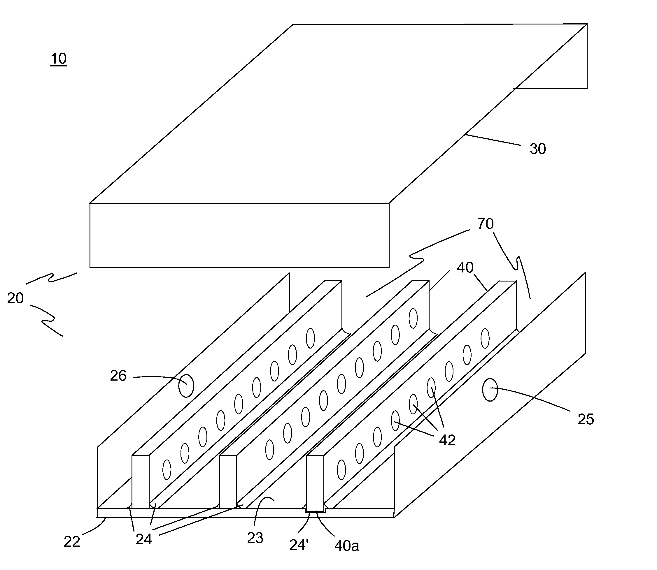
[0021] The preferred embodiment(s) of the present invention is illustrated in FIGS. 1-4. FIG. 1 shows one embodiment of a heat exchanger 10 of the present invention in a separated view. Heat exchanger 10 includes a housing 20 with a fluid inlet 25 and a fluid outlet 26 and a plurality of fin members 40 enclosed within housing 20. Housing 20 has a thermally conductive portion 22 to which the plurality of fin members 40 are thermally connected.

[0022] In the preferred embodiment, housing 20 has a base 22 and a cover 30. Base 22 is made of a thermally conductive material and is the thermally conductive portion. Base 22 optionally and preferably includes a plurality of ribs 24 or grooves 24′ along an inside surface 23. It should be understood that both the base and cover may be made of thermally conductive material.

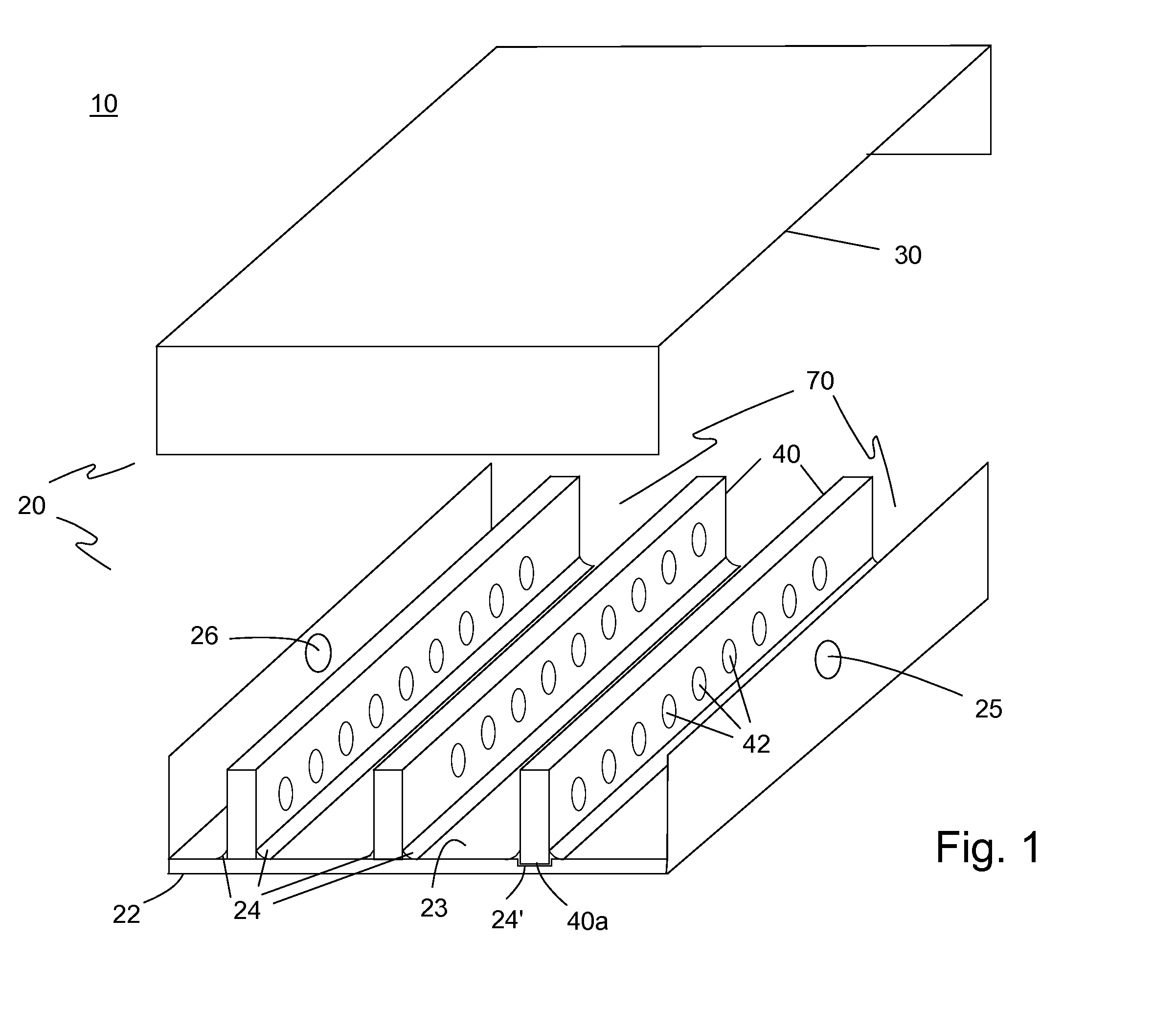
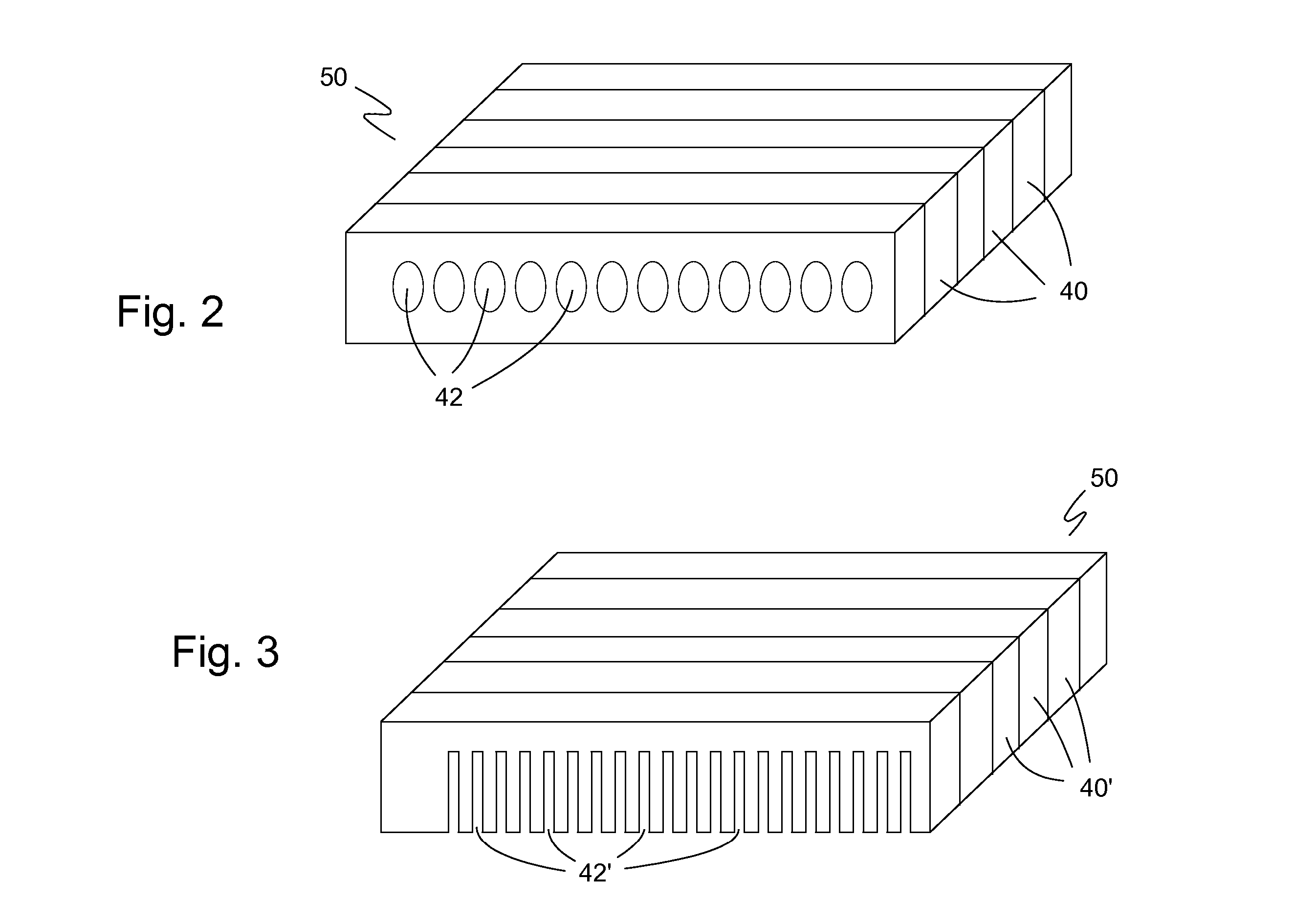
[0023] The plurality of fin members 40, which are made of a thermally conductive material, are thermally connected along a base edge 40a to the inside surface 23 of base 22 ...


PUM

PropertyMeasurementUnit
thermally conductiveaaaaaaaaaa
distanceaaaaaaaaaa
period of timeaaaaaaaaaa

Abstract

A fluid heat exchanger has a housing having a thermally conductive base, a plurality of fin members connected to the base in a parallel, spaced relationship, a heat exchanger fluid inlet on one side of the plurality of fin members, and a heat exchanger fluid outlet on the opposite side of the plurality of fin members. The plurality of fin members each have a plurality of passageways and are arranged in the housing so that the passageways of one fin member are offset from the passageways of adjacent fin members.

Description

[0001] This application claims the benefit of US Provisional Patent Application No. 60 / 594,606, filed Apr. 22, 2005.BACKGROUND OF THE INVENTION [0002] 1. Field of the Invention [0003] The present invention relates to heat exchangers. Particularly, the present relates to fluid-based heat exchangers. [0004] 2. Description of the Prior Art [0005] Heat exchangers have been used in numerous applications and include air-cooled as well as liquid cooled heat exchangers. Liquid cooled heat exchangers typically include a manifold having a maze configuration where the fluid follows a continuous, tortuous path from the inlet port to the outlet port. This causes the fluid to flow over a greater distance within the manifold causing the fluid to remain in contact with the heating or cooling surface of the exchanger for a longer period of time. However, prior art heat exchangers are expensive to make and can be relatively large. [0006] Compact heat exchangers have also been developed that are more ...

Claims


Application Information

Patent Timeline
Patent Type & Authority Applications(United States)
IPC IPC(8): H05K7/20
CPCF28F3/02Y10T29/4935F28F7/02F28F3/12F28F2215/08
Inventor OTEY, ROBERT W.KAMINSKI, DAVID A.
Owner FERROTEC USA CORP
Why Eureka
Try Eureka