Vehicle ignition interlock systems with multiple alcohol sensors

a technology of ignition interlocking and vehicle, which is applied in the direction of electric devices, instruments, tractors, etc., can solve the problems of vehicle operation being disabled or becoming disabled, vehicle ignition being disabled, and vehicle being rendered inoperabl

Inactive Publication Date: 2006-10-26
MONITECH
View PDF31 Cites 23 Cited by
  • Summary
  • Abstract
  • Description
  • Claims
  • Application Information

AI Technical Summary

Benefits of technology

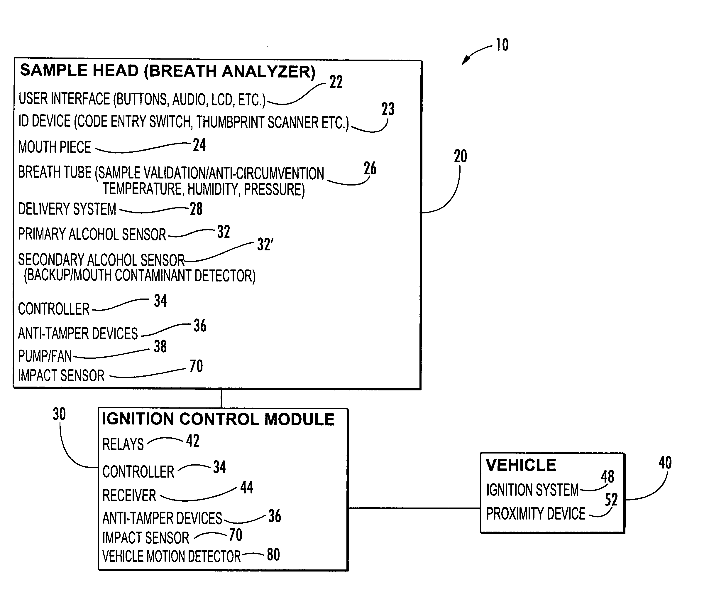
[0013] According to other embodiments of the present invention, the vehicle ignition interlock includes a user interface that is operably connected to the controller and that is configured to display operational messages. The controller may also provide audible operational messages and prompts via the user interface, including voice messages in one or more languages.
[0014] According to embodiments of the present invention, a vehicle ignition interlock system may also include an impact sensor that is physically attached to one or more portions of the vehicle ignition interlock system. The impact sensor is configured to detect impact events experienced by the vehicle ignition interlock system as a result of, for example, abuse by an individual. The vehicle ignition interlock system controller is configured to record impact events detected by the impact sensor and to provide a message (e.g., a warning) to the vehicle operator in response to the impact sensor detecting an impact event. The impact sensor may be an accelerometer or other device capable of detecting impacts.
[0015] According to embo...

Problems solved by technology

Vehicle operation by persons under the influence of alcohol is a well known safety problem in the United States and throughout the world.
If the driver's breath alcohol exceeds a preset limit, the vehicle's ignition is disabled and the vehicle is rendered inoperable.
If the driver either refuses to take a retest or if the driver's breath alcohol exceeds a preset limit, vehicle operation may be disabled or may become disabled within a preset period of time.
Operation of...

Method used


Image

  • Vehicle ignition interlock systems with multiple alcohol sensors
  • Vehicle ignition interlock systems with multiple alcohol sensors
  • Vehicle ignition interlock systems with multiple alcohol sensors

Examples


Embodiment Construction

[0018] The present invention now is described more fully hereinafter with reference to the accompanying drawing, in which preferred embodiments of the invention are shown. This invention may, however, be embodied in many different forms and should not be construed as limited to the embodiments set forth herein; rather, these embodiments are provided so that this disclosure will be thorough and complete, and will fully convey the scope of the invention to those skilled in the art.

[0019] It will be understood that when an element is referred to as being “on” another element, it can be directly on the other element or intervening elements may also be present. In contrast, when an element is referred to as being “directly on” another element, there are no intervening elements present. It will be understood that when an element is referred to as being “connected” or “attached” to another element, it can be directly connected or attached to the other element or intervening elements may a...


PUM


Abstract

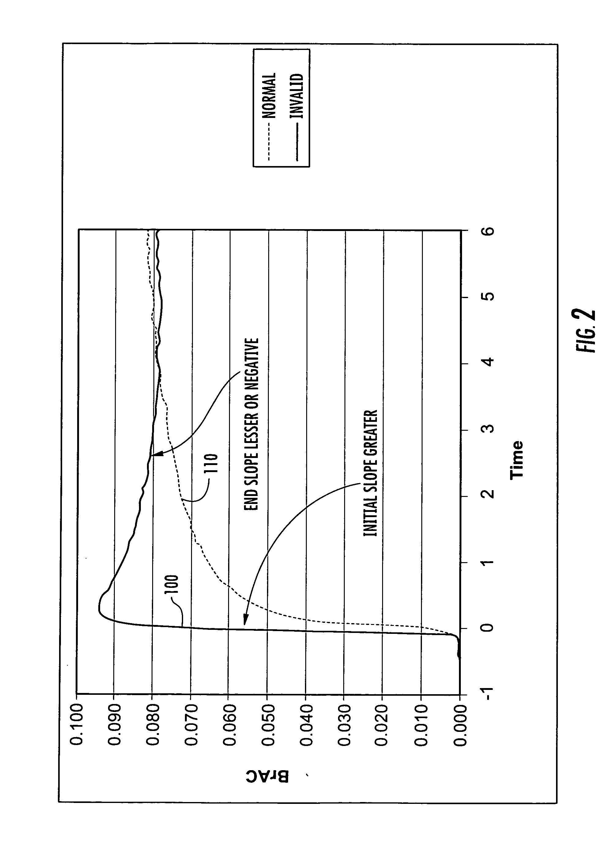
A vehicle ignition interlock system includes a breath analyzer and a controller operably connected to the breath analyzer and to an ignition system of the vehicle. The breath analyzer detects breath alcohol level of a vehicle operator and prevents vehicle ignition if a breath alcohol level is greater than or equal to a threshold value. The controller requires the vehicle operator to periodically take breath analyzer “retests” after vehicle ignition in order to allow vehicle operation to continue. The breath analyzer includes first and second alcohol sensors. The second alcohol sensor is a backup for the first alcohol sensor and becomes operational if the first alcohol sensor malfunctions. The first or second alcohol sensors may be a mouth contamination sensor that distinguishes between mouth contaminants and alcohol contained within a deep lung breath sample. The system also includes sensors configured to detect impact (abuse) and vehicle motion.

Description

FIELD OF THE INVENTION [0001] The present invention relates generally to sobriety testing devices and, more particularly, to vehicle ignition interlock systems. BACKGROUND OF THE INVENTION [0002] Vehicle operation by persons under the influence of alcohol is a well known safety problem in the United States and throughout the world. Thousands of deaths per year in the United States are attributable to drivers operating vehicles under the influence of alcohol. To address this problem, most states have established laws that prohibit operation of a vehicle by an individual with a blood alcohol content (BAC) greater than a preset value (e.g., 0.08% BAC). In addition, “ignition interlock” systems have been developed which are directly connected to a vehicle's ignition system and are designed to prevent vehicle operation by inebriated individuals. Many states require the installation of ignition interlock systems in the vehicles of individuals convicted of driving under the influence of al...

Claims


Application Information

Patent Timeline
IPC IPC(8): B60K28/00B60L1/00G08B23/00
CPCG01N33/4972B60K28/063
Inventor MOBLEY, LARRY J.MCMILLIN, BRIANEDWARDS, JIMMY H.LEWIS, JAMES R.
Owner MONITECH
Why Eureka
Try Eureka