Truss rod safety for irrigation spans

a technology of safety and irrigation spans, applied in watering devices, horticulture, agriculture, etc., can solve problems such as severe damage to equipment, and achieve the effect of adjusting the sensitivity of safety

Inactive Publication Date: 2006-10-26
LINDSAY CORP
View PDF30 Cites 13 Cited by
  • Summary
  • Abstract
  • Description
  • Claims
  • Application Information

AI Technical Summary

Benefits of technology

[0004] In one preferred form of the invention, the safety comprises an electrical switch mounted on one portion of the truss rod assembly and a switch actuator mounted on another portion of the assembly. When relative motion occurs between such two portions during slackening of the truss rod assembly, such motion causes the actuator to actuate the switch if the magnitude of the relative movement exceeds a predetermined amount. Activation of the switch can be used to send a signal to the system controller or to otherwise immediately disable drive motors associated with the driven ground wheels of the towers. In a particularly preferred embodiment, the switch and switch activator are mounted on two separate truss rods that in

Problems solved by technology

If one or more of the self-driven towers encounters an adverse circumstance such as a major obstruction, one or

Method used


Image

  • Truss rod safety for irrigation spans
  • Truss rod safety for irrigation spans
  • Truss rod safety for irrigation spans

Examples


Embodiment Construction

[0014] The present invention is susceptible of embodiment in many different forms. While the drawings illustrate and the specification describes certain preferred embodiments of the invention, it is to be understood that such disclosure is by way of example only. There is no intent to limit the principles of the present invention to the particular disclosed embodiments.

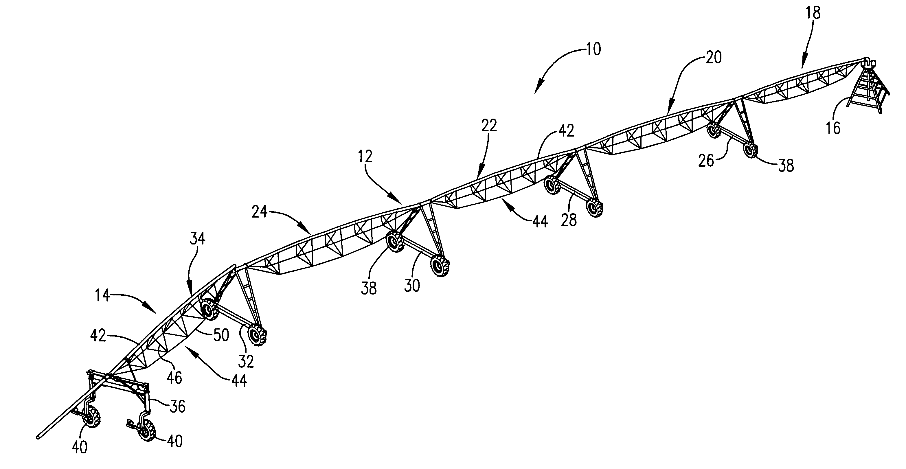
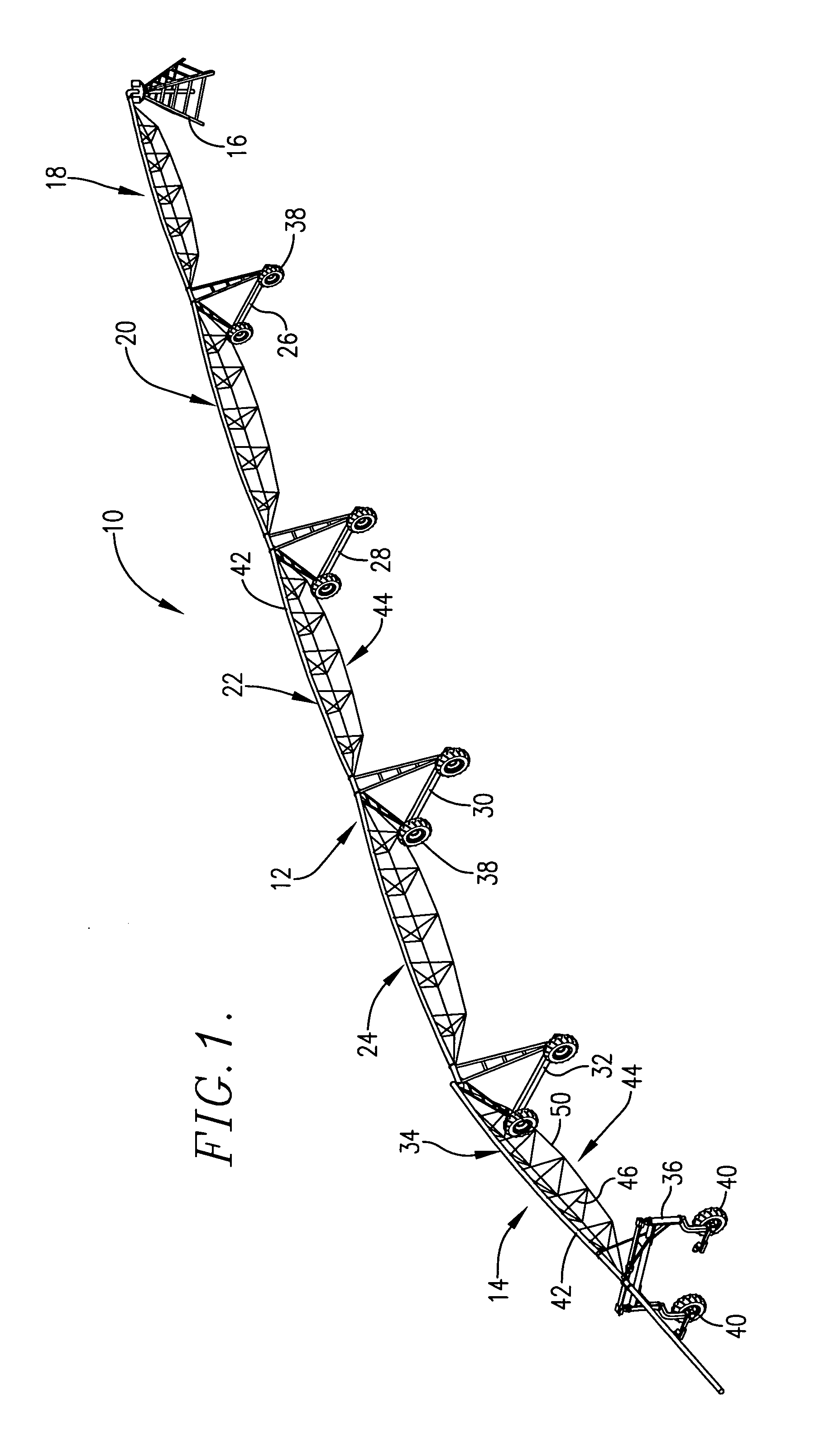
[0015] The irrigation system 10 selected for purposes of illustration in FIG. 1 comprises a center pivot system that includes a main section 12 and a corner section 14. Main section 12 is pivotally connected at its inner end to a stationary tower 16 having access to a well and is comprised of a number of interconnected spans 18, 20, 22 and 24 supported by mobile towers 26, 28, 30 and 32. Corner section 14 includes a single corner span 34 pivoted to the outer end of main section 12 at tower 32 and supported by its own steerable mobile tower 36. It will be appreciated that the safety of the present invention, as herein...


PUM


Abstract

A compression safety for a span of an agricultural irrigation system detects changes in the condition of truss rods associated with the framework of the span. When one portion of the truss rod assembly goes slack relative to another, such condition is detected by the safety to shut down the entire system. In a preferred embodiment, the safety is mounted at one of the V-braces forming part of the truss framework below the water conduit of the span. Truss rods are connected to and extend in opposite directions from the V-brace, one of such rods supporting a switch of the safety and the other supporting the switch actuator of the safety. The actuator comprises a long tubular member that is supported intermediate its ends by a fulcrum mount at the apex of the V-brace so that the operating lever of the switch is actuated by the actuator when it rocks about the fulcrum in response to a predetermined level of tension changes in the two truss rods.

Description

TECHNICAL FIELD [0001] The present invention relates to agricultural irrigation systems of the type wherein conduit spans are supported by mobile, self-propelled towers for advancing the spans through the field and, more particularly, to a safety mechanism for such systems that detects when one or more of the spans is subjected to untoward compression forces as a result of encountering an obstacle in the field or other adverse circumstance. BACKGROUND AND SUMMARY [0002] The conduits of irrigation spans associated with conventional irrigation systems are typically under compressive loading between mobile towers of the system and are maintained in such condition by rigidifying framework forming a part of each span. If one or more of the self-driven towers encounters an adverse circumstance such as a major obstruction, one or more of the spans may be subjected to an untoward level of compression that can severely damage the equipment. Consequently, various safeties have heretofore been...

Claims


Application Information

Patent Timeline
IPC IPC(8): B05B3/00
CPCA01G25/092
Inventor KORUS, THOMAS J.
Owner LINDSAY CORP
Why Eureka
Try Eureka