Swirl-reversal abradable labyrinth seal

Inactive Publication Date: 2006-10-26
ELLIOTT CO
View PDF27 Cites 30 Cited by
  • Summary
  • Abstract
  • Description
  • Claims
  • Application Information

AI Technical Summary

Benefits of technology

[0003] Briefly, according to this invention, there is provided an apparatus for restricting axial flow through the clearance between a rotating shaft and a seal stator and providing effective damping to improve rotor stability. The apparatus comprises an abradable labyrinth seal and swirl-reversing vanes upstream of the labyrinth seal. Preferably, the shaft comprises a first toothed axial section having a plurality of radially extending annular teeth and a second upstream toothed axial section having at least one radially extending annular tooth. Typically, the number of teeth in the second axial section is less than four. Between the first and second toothed sections, there is a cylindrical surface of diameter less than the diameter of the outer edges of the teeth. Fixed to the stator is a plurality of swirl-reversing vanes opposed to the cylindrical surface. Also

Problems solved by technology

Differential gas pressure in the axial direction along the shaft tends to cause leakage flow along the shaft from higher to lower pressure regions.
This leakage flow is detrimental for various reasons.
One of the detriments of leakage flow

Method used


Image

  • Swirl-reversal abradable labyrinth seal
  • Swirl-reversal abradable labyrinth seal
  • Swirl-reversal abradable labyrinth seal

Examples


Embodiment Construction

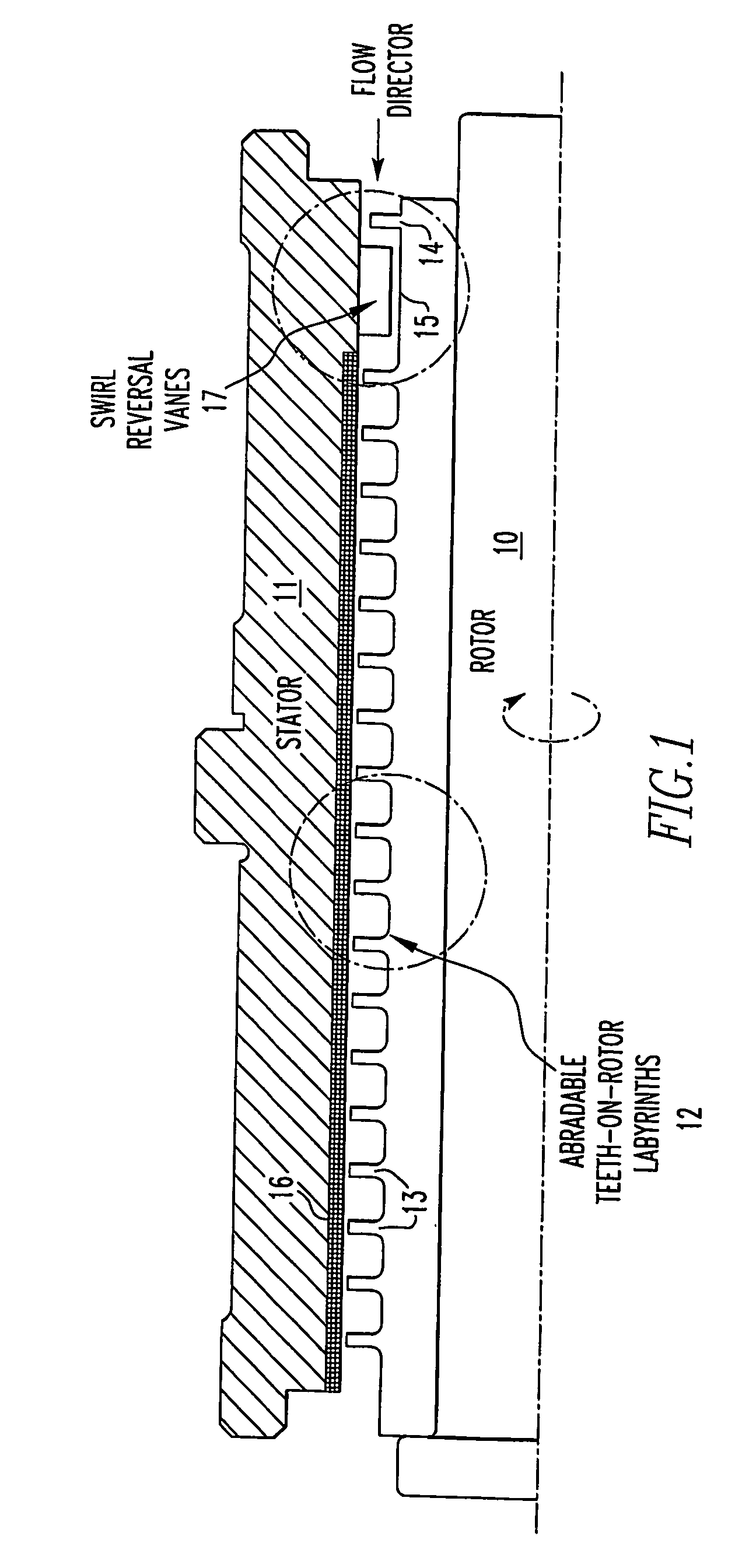
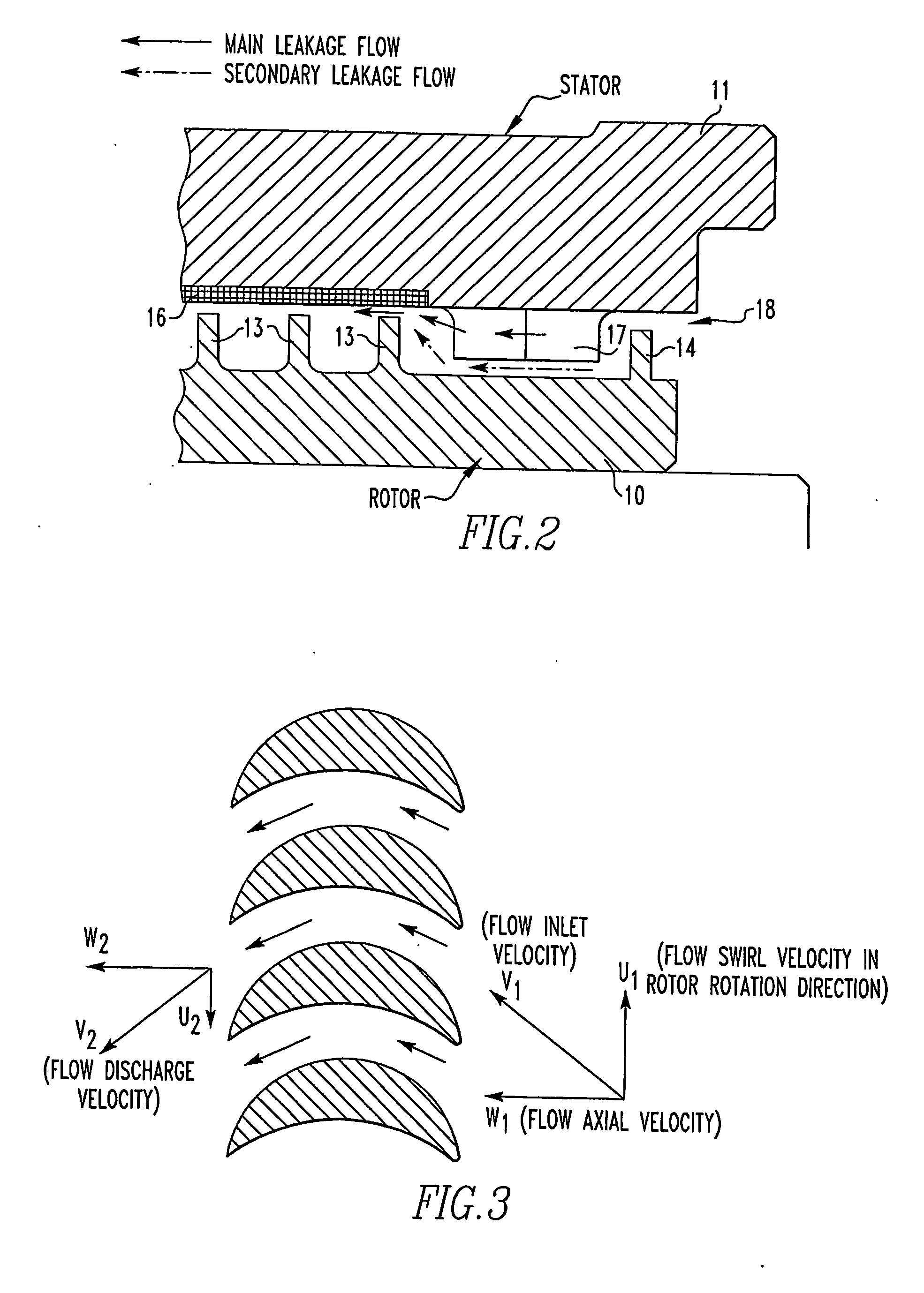
[0009] Referring to FIG. 1, the apparatus for restricting axial flow, according to this invention, comprises a rotor portion 10 and a stator seal portion 11. The rotor has a toothed section 12 comprising a labyrinth seal. There is a very small clearance between the tip of teeth 13 and the inner surface of the stator seal. The rotor has a second toothed section 14 upstream of the first toothed section having at least one tooth. Between the first and second toothed sections there is a section 15 that is a smooth cylindrical surface having a diameter less than the outer diameter of the tips of the labyrinth teeth. The surface of the stator radially outward of the plurality of teeth 13 in the first toothed section is coated with an abradable material 16. There may or may not be an abradable material radially outward of the second toothed section. If not, the clearance will be somewhat larger than being used with abradable materials. Swirl-reversal vanes 17 are fixed to the stator seal e...


PUM


Abstract

An apparatus for restricting axial flow through the clearance between a rotating shaft and a seal stator comprises an abradable labyrinth seal and swirl-reversal vanes upstream of the labyrinth seal. The shaft comprises a first toothed axial section having a plurality of annular teeth, a second upstream toothed axial section having a few annular teeth from one to three, and a section therebetween having a cylindrical surface of diameter less than the outer edge of the teeth of the toothed sections, the swirl-reversing vanes being fastened to the stator seal between the toothed sections.

Description

BACKGROUND OF THE INVENTION [0001] Centrifugal compressors are rotating machines. They are comprised of stationary portions referred to as stators and rotating portions known as rotors. The rotors are supported on journal bearings in the stator. Differential gas pressure in the axial direction along the shaft tends to cause leakage flow along the shaft from higher to lower pressure regions. This leakage flow is detrimental for various reasons. Hence, seals are positioned along the shaft to retard this leakage flow. In centrifugal compressors, use of labyrinth seals, and especially abradable labyrinth seals, are well known. Labyrinth seals provide a tortuous path along the shaft minimizing flow. Generally, labyrinth seals comprise a plurality of radial teeth extending from the stator or the shaft with a small radial clearance at the tips of the teeth. In order to make the clearance very small and yet to accommodate the unavoidable vibration of the shaft relative to the stator which w...

Claims


Application Information

Patent Timeline
IPC IPC(8): F16J15/447F04D29/10F04D29/66F16J15/44
CPCF16J15/445F16J15/4472F01D11/001F16J15/44F04D29/102F04D29/668F01D11/02
Inventor LI, JIMINGDE CHOUDHURY, PRANABESH
Owner ELLIOTT CO
Why Eureka
Try Eureka