Crushable structure manufactured from mechanical expansion

a technology of mechanical expansion and crushing initiators, which is applied in the direction of bumpers, vehicle components, vehicular safety arrangments, etc., can solve the problems of reducing the overall component efficiency of crushing initiators, reducing the load following the initiation of initiation, and reducing the load needed, so as to achieve a constant thickness and a larger cross section

Inactive Publication Date: 2006-10-26
SHAPE CORP
View PDF40 Cites 51 Cited by
  • Summary
  • Abstract
  • Description
  • Claims
  • Application Information

AI Technical Summary

Benefits of technology

[0007] An aspect of the present invention is to provide a crush member for a vehicle having frame rails comprising a tube having a first end configured to be connected to the frame rails of the vehicle and a second end configured to be connected to a bumper. The tube has a polygonal cross section. The tube also has a constant thickness from the first end to the second end. The tube further has a taper along an axial direction from the first end to the second end, the tube having a larger cross section at the first end and a smaller cross section at the second end. The tube is configured to crush to absorb impact energy upon an axial or near axial load.

Problems solved by technology

Crush initiators can reduce the overall component efficiency due to the erratic F-d behavior associated with the crush initiator.
A drawback to crush initiators is that the load following the onset of initiation is lower than the load necessary to initiate the crush.
This causes a peak and valley type of response where each valley represents a loss in efficiency due to a loss in load.
There exists materials and manufacturing processes that in tandem can be used to produce highly efficient energy management components, but all too often the cost of the product will limit its commercial acceptance and usage.

Method used


Image

  • Crushable structure manufactured from mechanical expansion
  • Crushable structure manufactured from mechanical expansion
  • Crushable structure manufactured from mechanical expansion

Examples


Embodiment Construction

[0022] For purposes of description herein, the terms “upper,”“lower,”“right,”“left,”“rear,”“front,”“vertical,”“horizontal,” and derivatives thereof shall relate to the invention as orientated in FIG. 1. However, it is to be understood that the invention may assume various alternative orientations, except where expressly specified to the contrary. It is also to be understood that the specific devices and processes illustrated in the attached drawings, and described in the following specification are simply exemplary embodiments of the inventive concepts defined in the appended claims. Hence, specific dimensions and other physical characteristics relating to the embodiments disclosed herein are not to be considered as limiting, unless the claims expressly state otherwise.

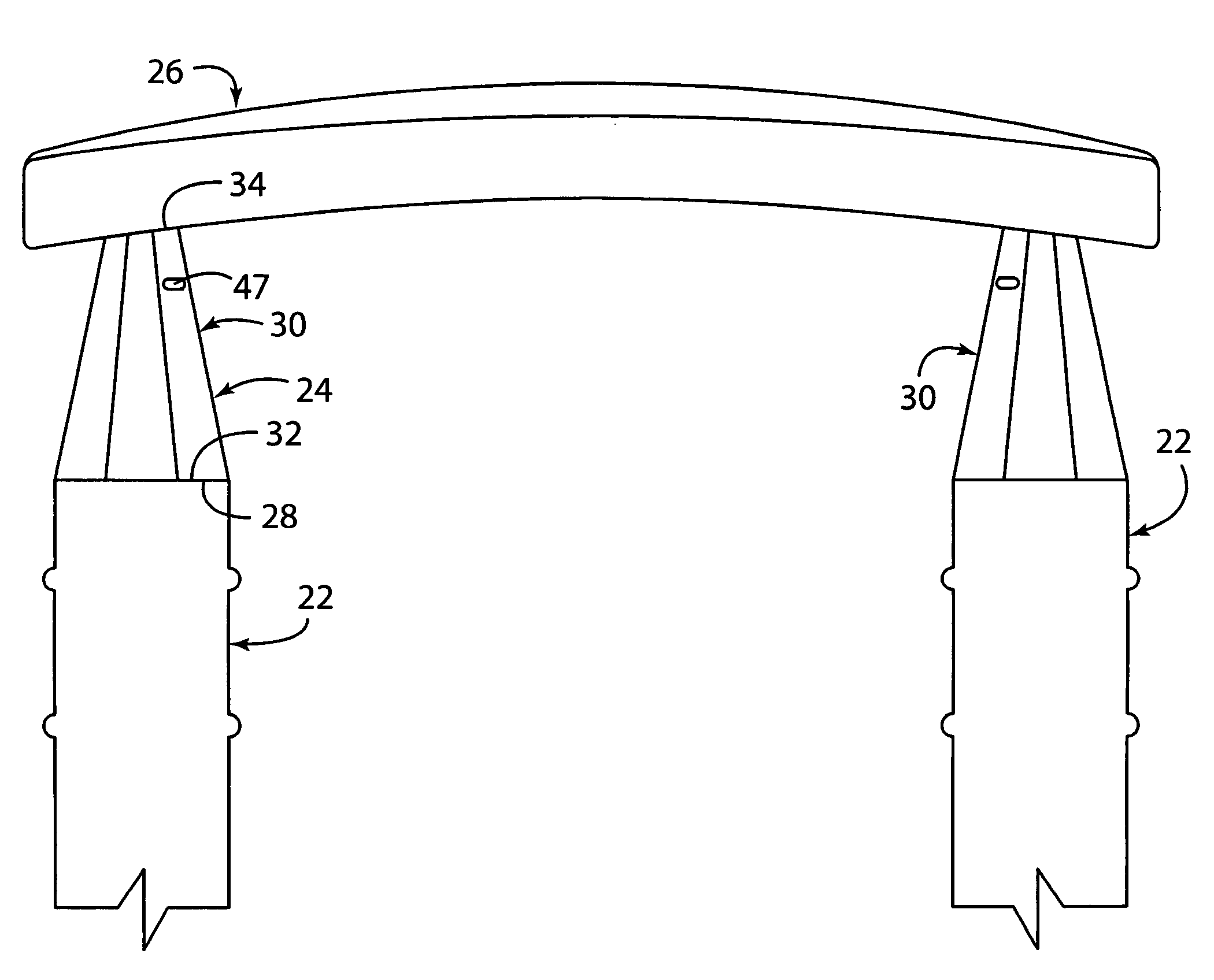
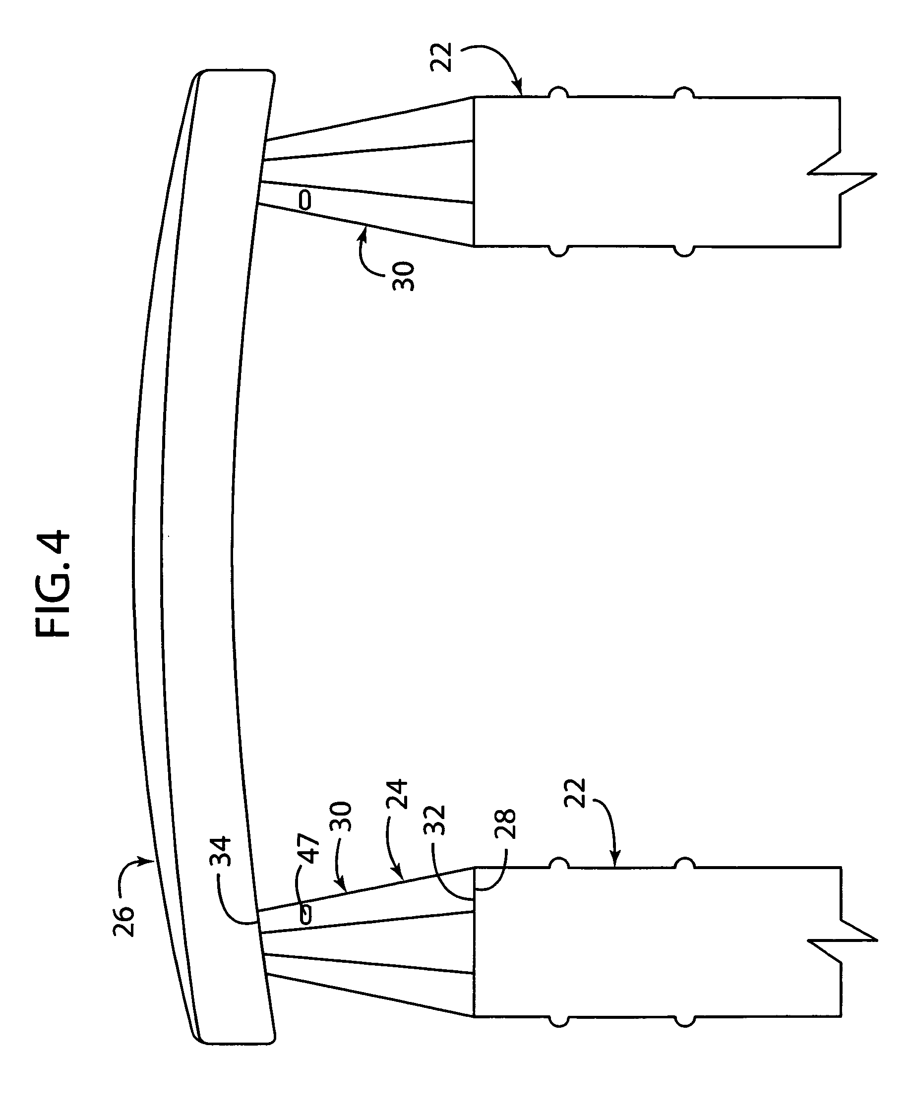
[0023] The reference number 20 (FIG. 4) generally designates a bumper system for a vehicle according to the present invention. In the illustrated example, the bumper system 20 comprises a frame rail 22, a crush membe...


PUM

PropertyMeasurementUnit
thicknessaaaaaaaaaa
impact energyaaaaaaaaaa
absorbs energyaaaaaaaaaa

Abstract

A crush member for a vehicle having frame rails comprising a tube having a first end configured to be connected to the frame rails of the vehicle and a second end configured to be connected to a bumper. The tube has a constant thickness from the first end to the second end. The tube further has a taper along a axial direction from the first end to the second end, the tube having a larger cross section at the first end and a smaller cross section at the second end. The tube is configured to crush to absorb impact energy upon an axial or near axial load.

Description

FIELD OF THE INVENTION [0001] The present invention relates to a beam design that absorbs energy efficiently while deforming. Applications for this invention could include vehicle bumper systems, side impact bars, and sill plates. BACKGROUND OF THE INVENTION [0002] Various components on the front and rear of a vehicle are designed to crush upon axial or near axial loading. The crushing of these components absorbs impact energy associated with collisions. Absorption of the impact energy helps to reduce vehicle damage and protect occupants within the vehicle from bodily harm. [0003] Heretofore, the components included bumper brackets 10 and frame rail ends 12 (FIG. 1). Bumper brackets 10 have typically been made from two separate stampings 14 that are welded together to form a tubular design (see FIG. 2). The tubular design of the bumper brackets 10 can taper from one end to the other end, thereby providing additional bending stiffness for off axis loading (e.g., near axial loading) y...

Claims


Application Information

Patent Timeline
Patent Type & Authority Applications(United States)
IPC IPC(8): B60R19/26
CPCB21C37/158B60R19/34B21C37/18
Inventor GLASGOW, SCOTT C.HEATHERINGTON, DAVID W.LYONS, BRUCE W.
Owner SHAPE CORP
Why Eureka
Try Eureka