Charge control device

a control device and charge technology, applied in the direction of charge maintainance charging/discharging, instruments, transportation and packaging, etc., can solve the problems of reducing discharge capacity, difficult to select an appropriate charge level in the aforementioned method, and reducing the charging rate, so as to prolong the cycle life of the secondary battery

Active Publication Date: 2006-10-26
PANASONIC CORP
View PDF4 Cites 11 Cited by
  • Summary
  • Abstract
  • Description
  • Claims
  • Application Information

AI Technical Summary

Benefits of technology

[0012] In order to solve the conventional problems described above, an object of the present invention is to provide a charge control device capable of extending a cycle life of the secondary battery.

Problems solved by technology

On the other hand, when the charging voltage is low, the charging rate becomes lower, thus decreasing the discharge capacity.
However, since the charged level of the secondary battery significantly varies depending on the condition of use, it is very difficult to select an appropriate charged level in the aforementioned method.
However, in a conventional control method based on a remaining capacity of the secondary battery, the charged level may not be controlled as desired since a precision for detecting the remaining capacity is reduced as characteristics of the secondary battery vary over time.

Method used


Image

  • Charge control device
  • Charge control device
  • Charge control device

Examples


first embodiment

[0022] (First Embodiment)

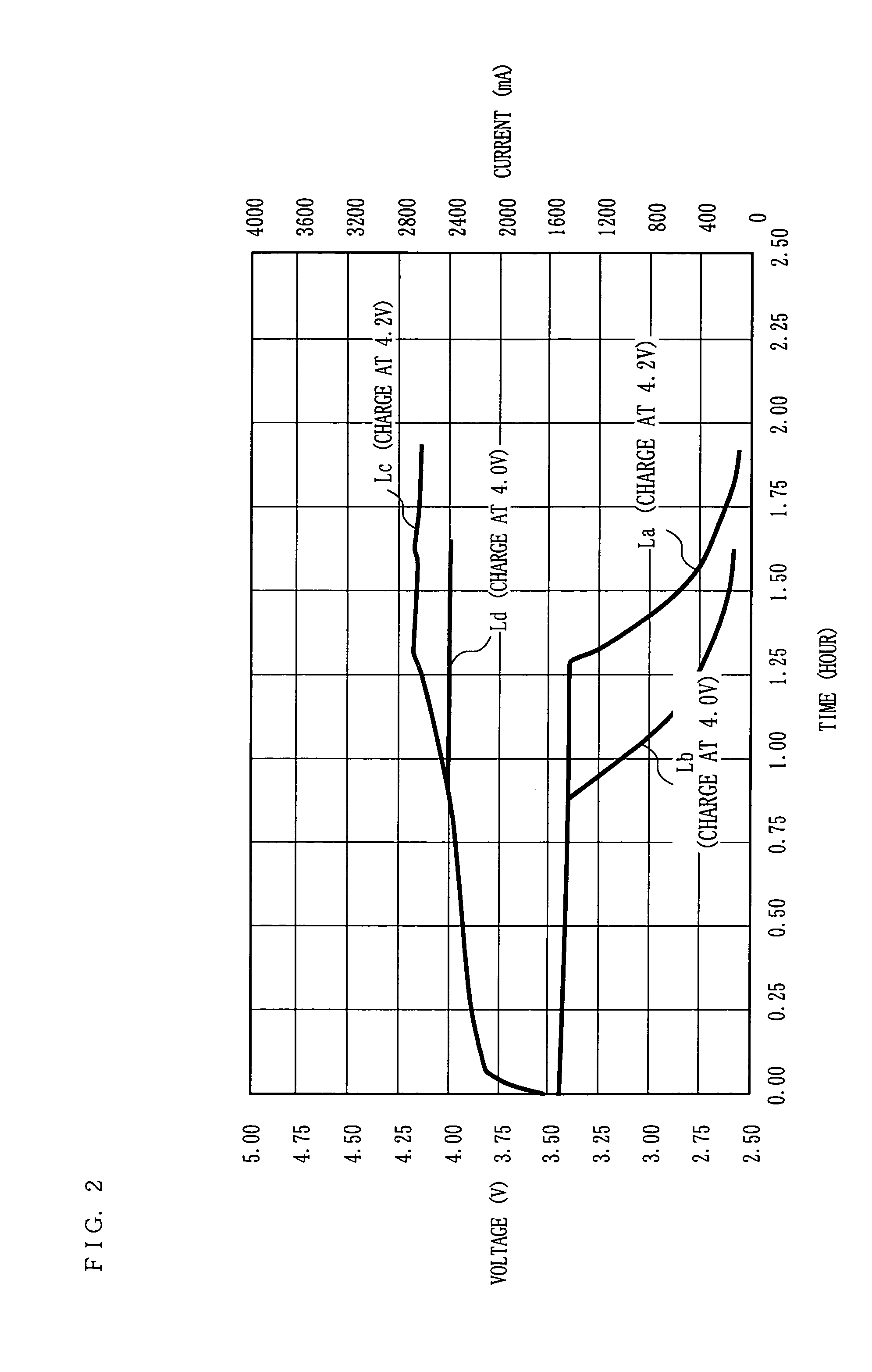
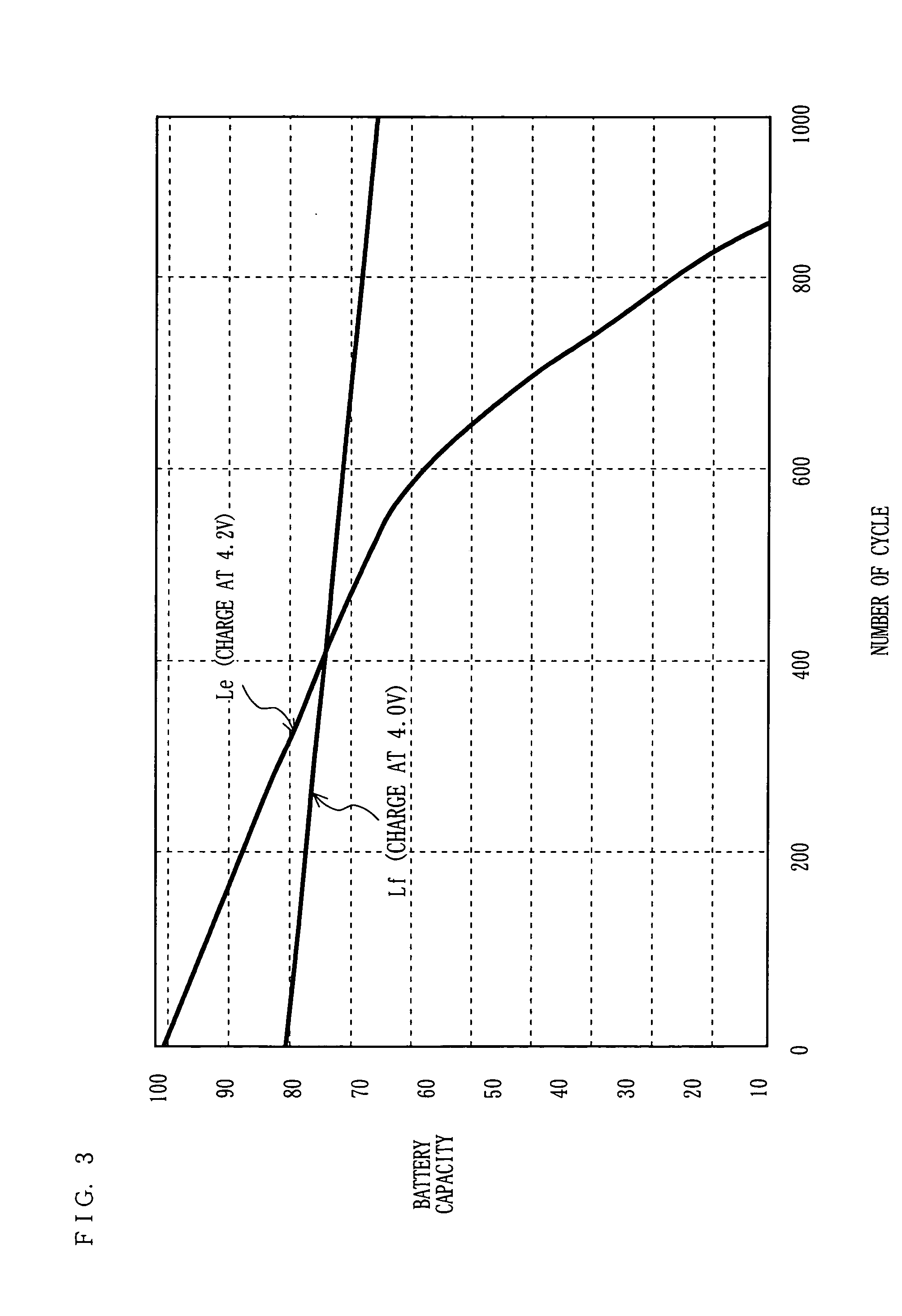
[0023] Hereinafter, with reference to FIGS. 1, 2, 3, and 4, a charge control device according to a first embodiment of the present invention is described.

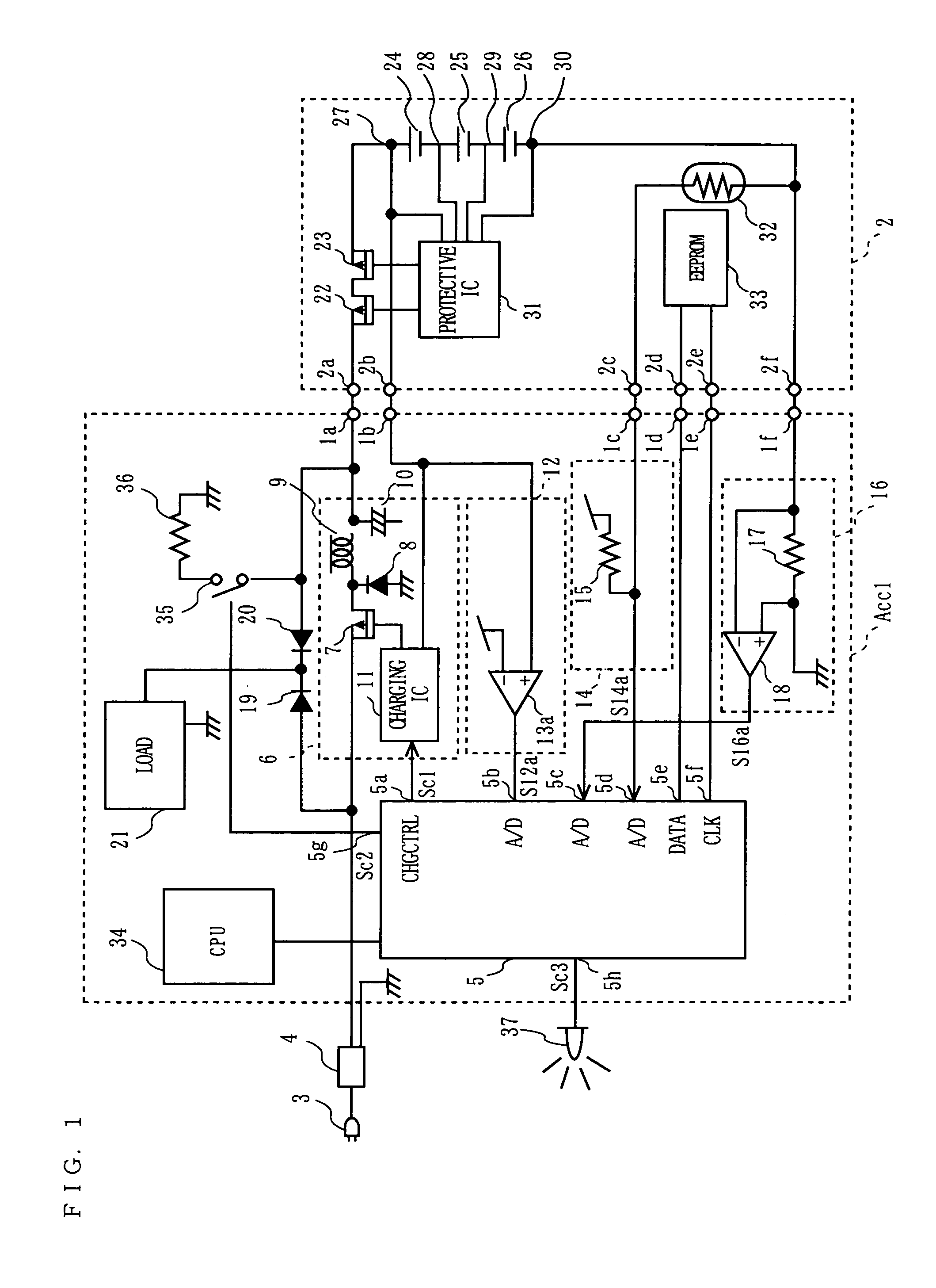
[0024] As shown in FIG. 1, a charge control device ACC1 is connected to a battery pack 2, and used for controlling a charged level of the battery pack 2. A terminal 1a, a terminal 1b, a terminal 1c, a terminal 1d, a terminal 1e, and a terminal 1f included in the charge control device ACC 1, and a terminal 2a, a terminal 2b, a terminal 2c, a terminal 2d, a terminal 2e, and a terminal 2f included in the battery pack 2, are detachably connected to each other respectively.

[0025] The charge control device ACC1 includes a microcontroller 5, a charge circuit 6, a voltage detection circuit 12, a temperature detection circuit 14, a current detection circuit 16, a diode 19, a diode 20, a load 21, a CPU 34, a switch 35, and a discharge resistor 36. A power is supplied at a predetermined voltage to the charge control...

second embodiment

[0073] (Second Embodiment)

[0074] Hereinafter, with reference to FIG. 4, the charge control device according to a second embodiment of the present invention is described. Firstly, its basic concept is described. As shown in FIG. 4, the charge control device ACC2 in the second embodiment is different from the charge control device ACC1 shown in FIG. 1 in that the charge control device ACC2 further comprises the FET 38 between the power supply unit 4 and the charge circuit 6, and the load 21. Furthermore, the microcontroller 5 in the charge control device ACC1 is replaced with the microcontroller 5′ in the charge control device ACC2. In addition to the first charge control signal Sc1 and the third charge control signal Sc3, the microcontroller 5′ has a function of generating a fourth charge control signal Sc4, which controls the FET 38 and the power supply circuit 39 of the load 21. Note that the second control signal Sc2 is not to be generated.

[0075] In the charge control device ACC2...


PUM


Abstract

A charge circuit 6 supplies a charging voltage (Vc) or a charging current to a secondary battery 2, 24 to 26 used for driving an appliance 21; a charged level setting device 5, Sc1 causes the charge circuit 6 to charge the secondary battery 2, 24 to 26 to a predetermined charged level, and detection means 12 detects a charged level of the secondary battery 2; a discharge section 21, 5, Sc1 discharges the secondary battery 2; and control means operates the charge circuit 6 when the predetermined charged level is higher than the detected charged level, and discharges the secondary battery by the discharge section 21, 5, Sc1 when the predetermined charged level is lower than the detected charged level Thus, it is possible to provide a charge control device capable of extending a cycle life of a secondary battery.

Description

BACKGROUND OF THE INVENTION [0001] 1. Field of the Invention [0002] The present invention relates to a charge control device of a secondary battery used for driving an electronic appliance and the like. [0003] 2. Description of the Background Art [0004] A rechargeable secondary battery is widely used as a power supply of a portable electronic appliance or an electrical appliance (hereinafter, referred to as a “portable appliance”) such as a notebook type personal computer (hereinafter, referred to as a “notebook computer”), a digital video camera, a digital still camera, a mobile telephone and the like. The secondary battery used for the portable appliance needs to have a small size, a light weight, a high capacity, a low memory effect, and a long life. Recently, a lithium ion secondary battery (hereinafter, referred to as a “lithium ion battery”) has been developed as a secondary battery which satisfies such demands. [0005] Compared with other small sized secondary batteries such a...

Claims


Application Information

Patent Timeline
Patent Type & Authority Applications(United States)
IPC IPC(8): H02J7/00
CPCH02J7/0075H02J7/0069
Inventor WANIBUCHI, TOHRU
Owner PANASONIC CORP
Why Eureka
Try Eureka