Circuit and method for controlling step-up/step-down DC-DC converter

a dc-dc converter and step-up/step-down technology, applied in the direction of dc-dc conversion, power conversion systems, instruments, etc., can solve the problems that dc-dc converter b>20/b> fails to sufficiently reduce operation loss, and achieve the effect of reducing operation loss

Inactive Publication Date: 2006-10-26
FUJITSU MICROELECTRONICS LTD
View PDF9 Cites 28 Cited by
  • Summary
  • Abstract
  • Description
  • Claims
  • Application Information

AI Technical Summary

Benefits of technology

[0017] The present invention provides a circuit and method for controlling a step-up / step-down DC-DC converter that reduces operation loss caused by on and off operations of transistors.

Problems solved by technology

Thus, the DC-DC converter 20 fails to sufficiently reduce operation loss.

Method used


Image

  • Circuit and method for controlling step-up/step-down DC-DC converter
  • Circuit and method for controlling step-up/step-down DC-DC converter
  • Circuit and method for controlling step-up/step-down DC-DC converter

Examples


Embodiment Construction

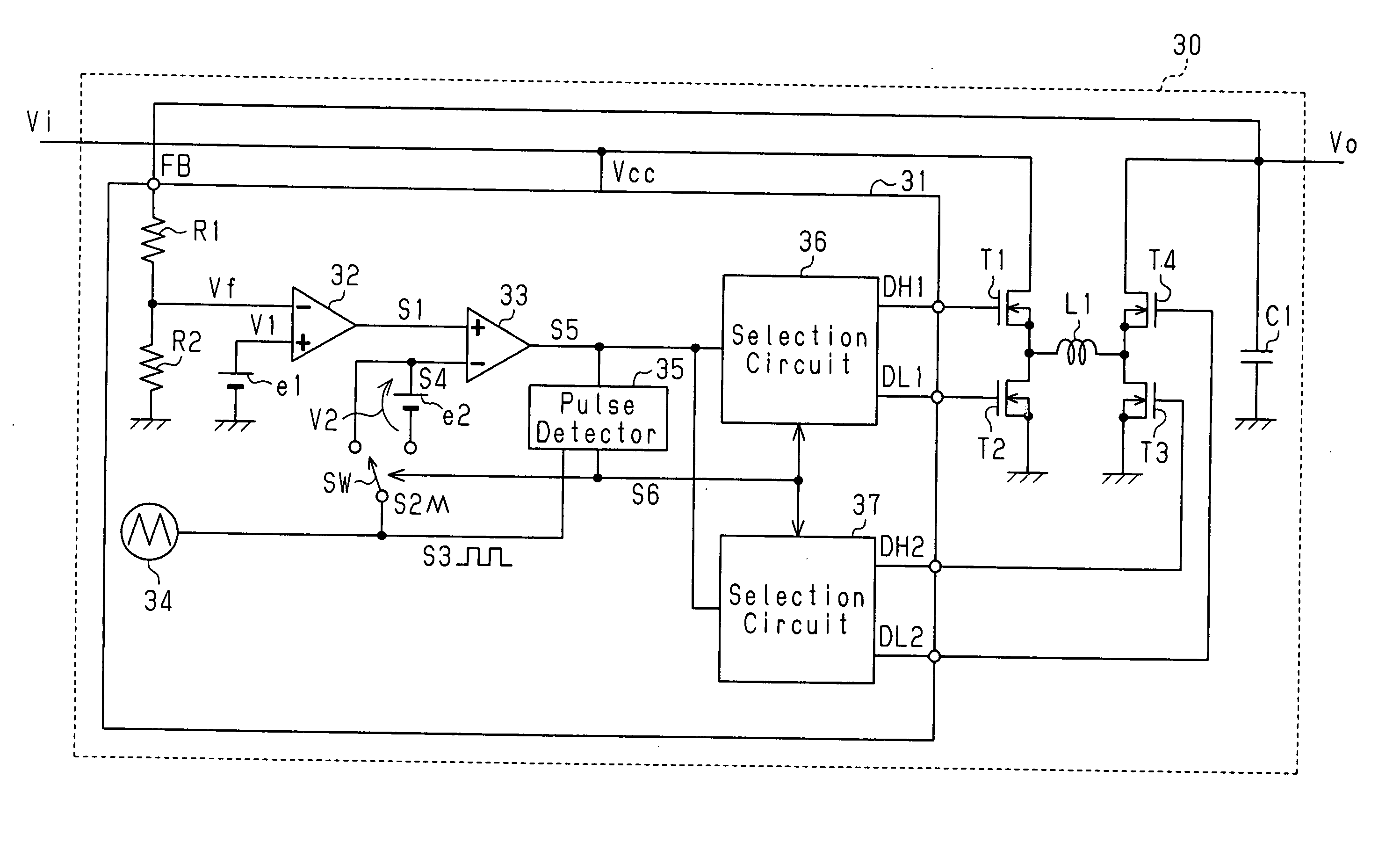
[0034] A DC-DC converter 30 according to a preferred embodiment of the present invention will now be described with reference to FIGS. 3 to 8.

[0035] The DC-DC converter 30 includes a control circuit 31, output transistors T1 to T4, a choke coil L1, and a smoothing capacitor C1. Each of the transistors T1 to T4 is preferably an N-channel MOS transistor.

[0036] The control circuit 31 provides the gate of each of the transistors T1 to T4 with a control signal. More specifically, the control circuit 31 provides the gate of the first transistor T1 with a control signal DH1, and the gate of the second transistor T2 with a control signal DL1. Further, the control circuit 31 provides the gate of the third transistor T3 with a control signal DH2, and the gate of the fourth transistor T4 with a control signal DL2.

[0037] The first transistor T1 has a drain supplied with input voltage Vi and has a source connected to a first terminal (input side terminal) of the choke coil L1. The second tran...


PUM


Abstract

A step-up/step-down DC-DC converter for reducing loss caused by activation and inactivation of transistors. An error amplifier included in a control circuit generates an error signal in accordance with voltage difference between an output voltage and a reference voltage. A PWM comparator compares a triangular wave signal and the error signal to generate a control pulse signal having a pulse width that is in accordance with the voltage difference between the output voltage and the reference voltage. A pulse detector monitors the control pulse signal and generates a mode switch signal for switching the operation mode of the DC-DC converter in accordance with a monitoring state of the control pulse signal. A switch provides the PWM comparator with the triangular wave signal or an offset signal, which is generated by adding an offset voltage to the triangular wave signal, in response to the mode switch signal.

Description

CROSS-REFERENCE TO RELATED APPLICATIONS [0001] This application is based upon and claims the benefit of priority from the prior Japanese Patent Application No. 2005-123798, filed on Apr. 21, 2005, the entire contents of which are incorporated herein by reference. BACKGROUND OF THE INVENTION [0002] The present invention relates to a DC-DC converter, and more particularly, to a circuit and method for controlling a step-up / step-down DC-DC converter. [0003] Portable electronic devices, such as notebook computers and game machines, incorporate a plurality of semiconductor integrated circuit devices. Each semiconductor integrated circuit device included in an electronic device is supplied with operating power from a battery. The output voltage of a battery decreases as the battery is discharged. Electronic devices use a DC-DC converter to keep the operating power voltage constant. Three types of DC-DC converters are known, namely, a step-down DC-DC converter, a step-up DC-DC converter, an...

Claims


Application Information

Patent Timeline
Patent Type & Authority Applications(United States)
IPC IPC(8): G05F1/00
CPCH02M3/1582H02M3/155
Inventor YOSHINO, TAKAHIRO
Owner FUJITSU MICROELECTRONICS LTD
Why Eureka
Try Eureka