Determining mobile terminal positions using assistance data transmitted on request

a technology of assistance data and mobile terminals, applied in the direction of instruments, measurement devices, beacon systems, etc., can solve the problems of temporary inability to determine the position of the terminal, general error in the position determination,

Inactive Publication Date: 2006-10-26
SOUND VIEW INNOVATIONS
View PDF7 Cites 57 Cited by
  • Summary
  • Abstract
  • Description
  • Claims
  • Application Information

AI Technical Summary

Benefits of technology

[0035] Moreover, the processing means may manage and then store in the database a three-dimensional model of the communication network based on corresponding cell identifiers and information data and / or auxiliary data. They may equally extract from the database a portion of the three-dimensional model of the communication network representing the three-dimensional model of the cell in which the requesting terminal is situated, in order to transmit thereto the portion of the 3D model representing the terrain of the cell in which it is situated. This enriches the meshing (geographical position / system time) and may enable the position of the mobile terminal to be determined with only three satellites in view (in which case there are only three independent unknowns, as the altitude Z is known for each pair (x, y)).

Problems solved by technology

Consequently, the position determined is generally affected by errors if at least one of the signals received from a satellite in view is of poor quality, which occurs relatively frequently, especially in uneven and congested environments.
It may even be temporarily impossible to determine the position of the terminal, even though the signals coming from the other satellites in view are of good quality.

Method used


Image

  • Determining mobile terminal positions using assistance data transmitted on request
  • Determining mobile terminal positions using assistance data transmitted on request
  • Determining mobile terminal positions using assistance data transmitted on request

Examples


Embodiment Construction

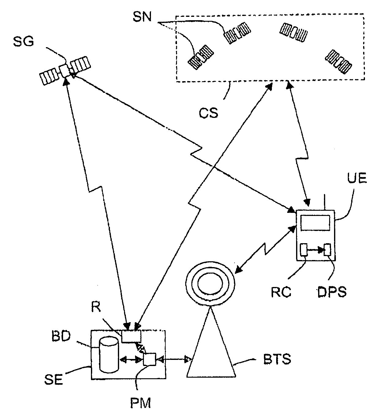
[0043] The invention relates to determining the positions of mobile terminals in a telecommunication installation.

[0044] In the present context, the expression “telecommunication installation” refers to an installation including at least one communication network communicating with mobile terminals and an “assistance” (or aid) system for broadcasting assistance data, and in particular complementary navigation data concerning a positioning system, for example a satellite positioning system.

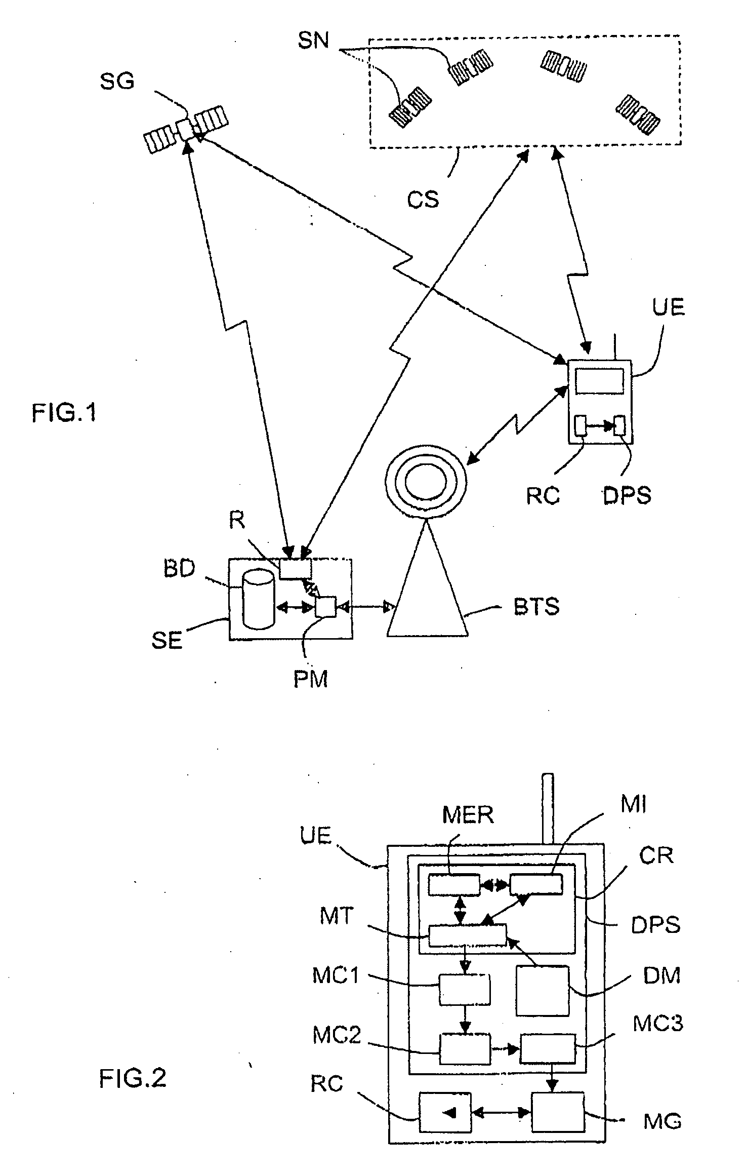
[0045] Moreover, in the present context, the expression “mobile terminal” (UE), refers to any type of terminal capable of receiving at least signals containing navigation data from the satellite positioning network and assistance data from the assistance system. They could therefore be simple portable satellite positioning devices, or devices on a land, sea or air vehicle and implementing at least one application linked to positioning, or mobile telephones, personal digital assistants (PDA) or la...


PUM


Abstract

A mobile terminal (UE) comprises means (CR) for acquiring pseudo-random codes modulating signals received from positioning satellites (SN) in view belonging to a constellation (CS) and related to a reference time, and computation means (MC1-MC3) for determining its position received from the acquired codes and from navigation data contained in the signals. The acquisition means (CR), on receiving assistance data representing an approximate reference time and the approximate position of the terminal (UE), determine estimated positions of the satellites, estimated distances between the terminal and each of the satellites in view and associated Doppler effects as a function of pairs of hypotheses relating to the approximate reference time and the approximate position, and then determine a signal replica for each pair of hypotheses corresponding to the estimated positions and distances and to the associated Doppler effects over a selected time interval, and select the pair of hypotheses corresponding to the signal replica having the maximum correlation with the signal received during the time interval in order to determine the pseudo-random codes modulating the received signals.

Description

BACKGROUND OF THE INVENTION [0001] The invention relates to determining the position of mobile terminals by satellites. [0002] In the present context, the expression “mobile terminal” refers equally to devices (or receivers) dedicated exclusively to satellite positioning and communication terminals equipped with a satellite positioning device, for example mobile telephones or personal digital assistants (PDA), where applicable of the communicating type. [0003] As the person skilled in the art knows, satellite positioning comprises two steps. In the first or acquisition step, the mobile terminal in question determines the pseudo-random codes modulating signals coming from satellites that are “in view” and belong to a constellation of positioning satellites relative to a reference time generally called the “system time”. The signals received from the satellites in view are “compared” to signal replicas resulting from hypotheses as to the system time and as to the timing frequency of t...

Claims


Application Information

Patent Timeline
Patent Type & Authority Applications(United States)
IPC IPC(8): G01S5/14G01S1/00G01S19/07G01S19/25
CPCG01S19/258G01S19/07G01S19/072G01S19/23G01S19/235
Inventor MONNERAT, MICHELMASSON, ARNAUDLOBERT, BRUNO
Owner SOUND VIEW INNOVATIONS
Why Eureka
Try Eureka