
Illumination unit and image projection apparatus having the same

a technology of illumination unit and projection apparatus, which is applied in the direction of lighting and heating apparatus, printing, instruments, etc., can solve the problems of limited brightness of projected images, array of led light sources, etc., and achieve the effect of high optical efficiency

Inactive Publication Date: 2006-10-26
SAMSUNG ELECTRONICS CO LTD
View PDF14 Cites 44 Cited by
  • Summary
  • Abstract
  • Description
  • Claims
  • Application Information

AI Technical Summary

Benefits of technology

[0009] The present invention provides an illumination unit which can implement a bright screen and in which high optical efficiency is obtained by increasing the number of small-sized light sources arranged in an array, and an image projection apparatus having the same.

Problems solved by technology

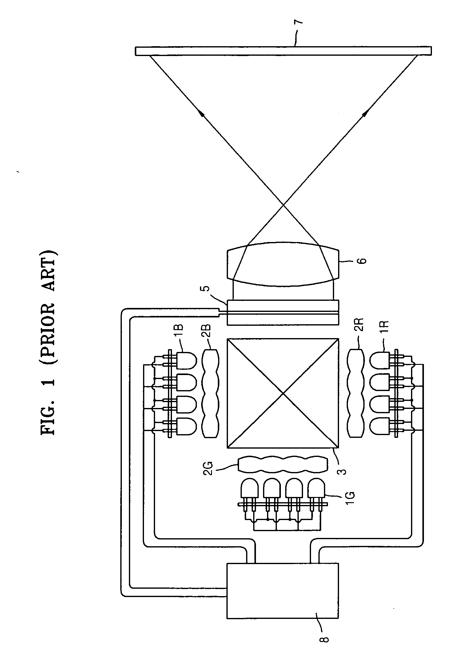
In the conventional image projection apparatus, since an emission area of the red, green, and blue LED light sources 1R, 1G, and 1B arranged in an array should not be larger than an effective display area of the LCD device 5, it is difficult to array a plurality of LED light sources, and thus, brightness of a projected image is limited.

Method used


Image

  • Illumination unit and image projection apparatus having the same
  • Illumination unit and image projection apparatus having the same
  • Illumination unit and image projection apparatus having the same

Examples


Embodiment Construction

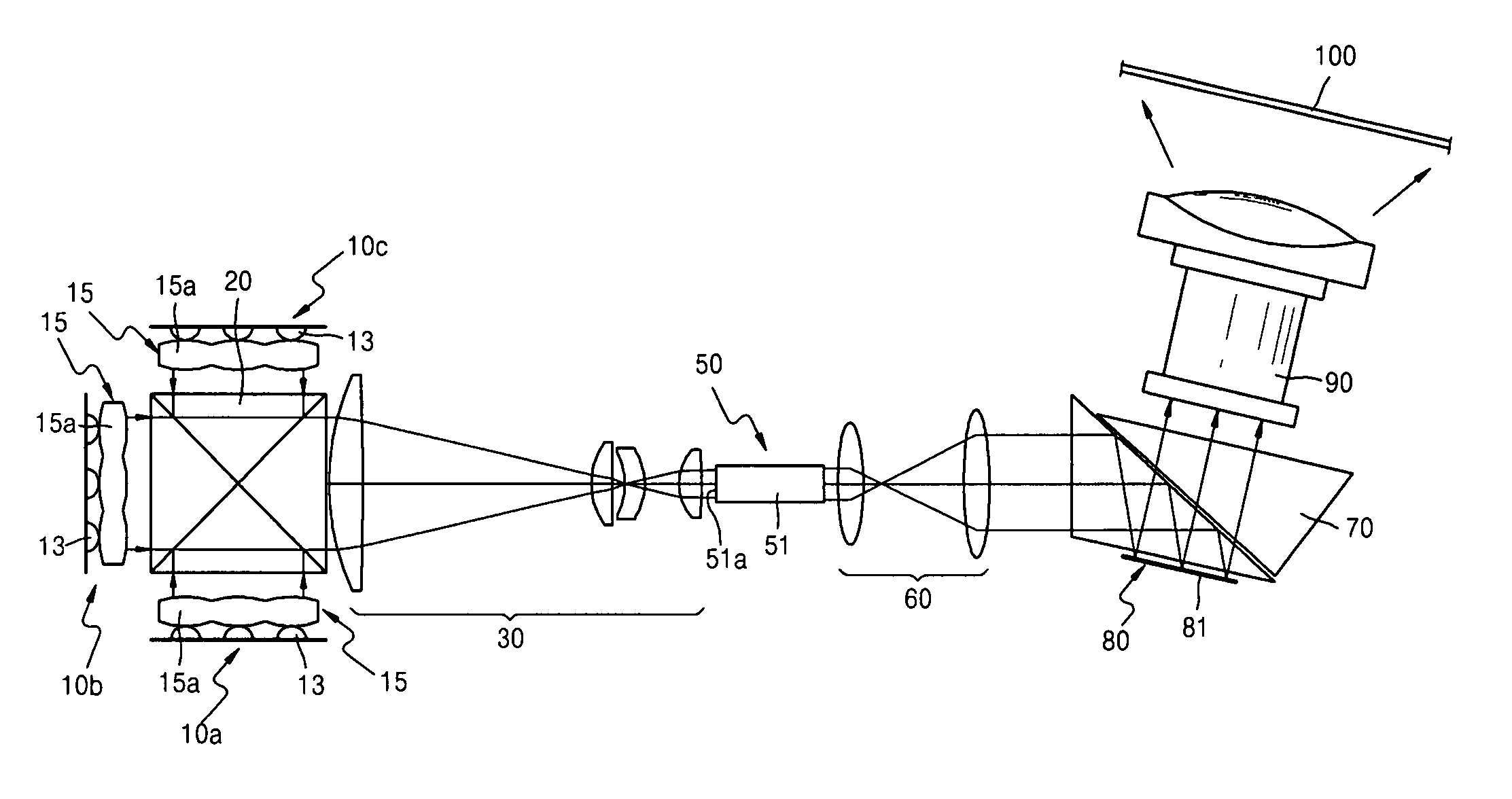
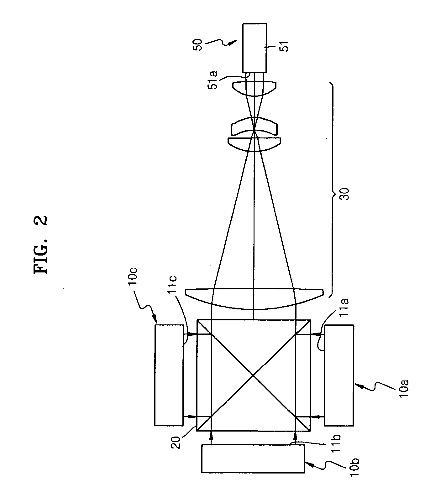
[0038]FIG. 2 is a schematic view of an optical configuration of an illumination unit according to an exemplary embodiment of the present invention, and FIG. 3 shows an exemplary optical path of light generated in a condensing lens system of FIG. 2.

[0039] Referring to FIGS. 2 and 3, the illumination unit includes at least one light source unit radiating a collimated light beam, an optical integrator 50 to make uniform incident light from the light source unit, and a condensing lens system 30 disposed between the light source unit and the optical integrator 50.

[0040] The illumination unit may be provided with a plurality of light source units. In this case, the light source units may radiate different colors. In FIGS. 2 and 3, the illumination unit is provided with first through third light source units 10a, 10b, and 10c radiating red, green, and blue light, respectively, for example.

[0041] When the illumination unit is provided with the first through third light source units 10a, ...


PUM


Abstract

An illumination unit and an image projection apparatus having the same are provided. The illumination unit includes: at least one light source unit which radiates a collimated light beam; an optical integrator which converts the collimated light beam from the at least one light source unit into a uniform light beam; and a condensing lens system, disposed between the at least one light source unit and the optical integrator, which reduces a cross-section of the collimated light beam emitted from the at least one light source unit and then guides the collimated light beam with the reduced cross-section to the optical integrator and has a 1:1 conjugate property between an object and an image of the object.

Description

CROSS-REFERENCE TO RELATED PATENT APPLICATIONS [0001] This application claims priority from Korean Patent Application No. 10-2005-0034158, filed on Apr. 25, 2005, in the Korean Intellectual Property Office, the disclosure of which is incorporated herein in its entirety by reference. BACKGROUND OF THE INVENTION [0002] 1. Field of the Invention [0003] Apparatuses and methods consistent with the present invention relate to an illumination unit for illuminating light and an image projection apparatus having the same and, more particularly, to an illumination unit which can implement a bright screen by arranging a larger number of small-sized light sources in an array, and an image projection apparatus having the same. [0004] 2. Description of the Related Art [0005] In general, illumination units include a light source radiating light and an illumination optical system transmitting light radiated by the light source. Illumination units are widely used in image projection apparatuses for ...

Claims


Application Information

Patent Timeline
IPC IPC(8): G03B21/14F21Y101/00
CPCF21K9/00F21K9/52F21Y2101/02G02B27/0994G03B27/547G03B21/208H04N9/3108H04N9/3152H04N9/3197G03B21/2013G03B21/2033G03B33/12F21K9/61F21Y2115/10F21K9/69G02B27/10
Inventor LEE, KYE-HOONLEE, WON-YONGLEE, YOUNG-CHOL
Owner SAMSUNG ELECTRONICS CO LTD
Learn More