Information processing apparatus and related method, image forming apparatus and related control method, program, and recording medium

Inactive Publication Date: 2006-10-26
CANON KK
View PDF36 Cites 82 Cited by
  • Summary
  • Abstract
  • Description
  • Claims
  • Application Information

AI Technical Summary

Benefits of technology

[0017] The present invention is directed to a technique that enables an operator of a host computer to easily perform the settings necessary for a finisher even when the finisher is not directly connected to an image forming appara

Problems solved by technology

In such a case, it will be difficult for an operator to accurately determine various settings necessary for the post-processing.
However, after the configuration (and contents) of the printer driver is fixed, the printer driver cannot recognize any function(s) of a newly connected finisher, e.g., a sheet cutting machine, a collating machine, or any other finisher other than the bookbinding machine.
Thus, the printer driver cannot control the print attributes requiring the use of a newly added and

Method used


Image

  • Information processing apparatus and related method, image forming apparatus and related control method, program, and recording medium
  • Information processing apparatus and related method, image forming apparatus and related control method, program, and recording medium
  • Information processing apparatus and related method, image forming apparatus and related control method, program, and recording medium

Examples


first exemplary embodiment

[Exemplary System Arrangement]

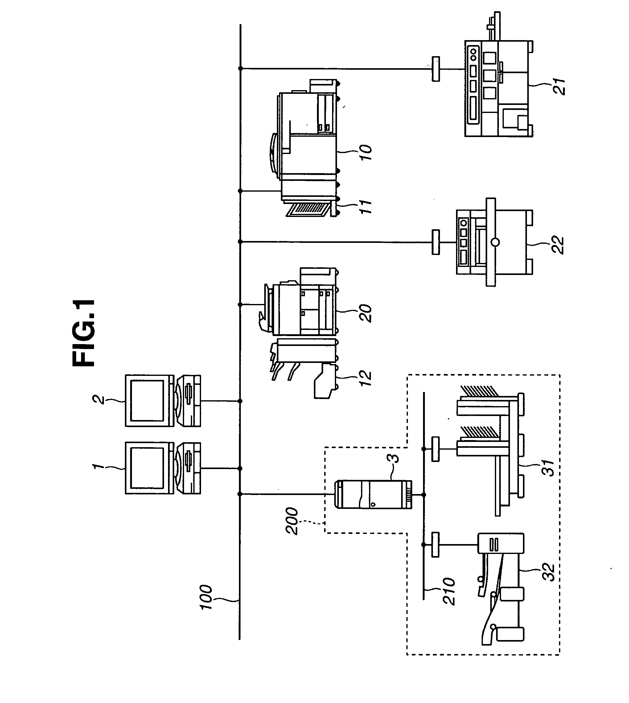
[0117]FIG. 1 is a diagram showing a schematic arrangement of an image forming system in accordance with an exemplary embodiment. As shown in FIG. 1, plural information processing apparatuses (hereinafter referred to as a “host computer”) 1 and 2 and plural image forming apparatuses 10 and 20, such as MFP (multi function peripheral), are connected to a network 100.

[0118] In this arrangement, for example, the image forming apparatuses 10 and 20 can receive print jobs from the host computers 1 and 2 via the network 100 and can process the received print jobs. Finishers 11 and 12, respectively connected via physical conveyance paths to the image forming apparatuses 10 and 20, can perform post-processing for printed products produced by the image forming apparatuses 10 and 20. The image forming apparatuses 10 and 20 can set the post-processing for the finishers 11 and 12. In this respect, the finishers 11 and 12 are referred to as “in-line finishers.”

[0119...

second exemplary embodiment

[0310] Next, a second exemplary embodiment of the present invention will be described with reference to the drawings. FIG. 34 is a schematic diagram illustrating the arrangement of an image forming system in accordance with the second exemplary embodiment. The image forming system of FIG. 34 is different from the image forming system of FIG. 28 in that the near-line finisher 2806 is replaced with a three-side sheet cutting machine 3406 that is connected to the network 100.

[0311] With respect to the connection of the three-side sheet cutting machine, the driver UI rearrangement application 512 performs the following display control. The connection of the near-line finisher in the present exemplary embodiment can be performed according to the procedure described in the first exemplary embodiment.

[Connection of Three-Side Sheet Cutting Machine and Property Information File]

[0312] The operator can connect the three-side sheet cutting machine 3406 (i.e., the near-line finisher) to the...

third exemplary embodiment

[0336]FIG. 40 is a schematic diagram illustrating an exemplary arrangement of an image forming system in accordance with a third exemplary embodiment. The image forming system of FIG. 40 includes an image forming apparatus 4001, a paper folding machine 4002, a sheet cutting machine 4003, a middle stitching machine 4004, and a casing-in bookbinding machine 4005. The paper folding machine 4002, the sheet cutting machine 4003, the middle stitching machine 4004, and the casing-in bookbinding machine 4005 can operate as near-line finishers. Besides the near-line finishers shown in FIG. 40, the image forming apparatus 4001 can communicate according to predetermined protocol with other near-line finishers, such as a stapler, a drilling machine, an inserting machine, and a collator, which are connected to a network 4006.

[0337]FIG. 41 is a schematic diagram illustrating the arrangement of the image forming apparatus 4001 in accordance with the third exemplary embodiment. The image forming a...


PUM


Abstract

An information processing apparatus displays a screen for enabling an operator to select settings for controlling a print output from an image forming apparatus and post-processing applied to a printed product by an independent post-processing apparatus. The post-processing apparatus includes an obtaining unit configured to obtain post-processing information from the post-processing apparatus and a display control unit configured to change contents of the setting screen based on obtained function information and display a changed setting screen. The image forming apparatus includes a determining unit configured to determine based on obtained function information whether the image forming apparatus can execute a print output accompanied by post-processing using the post-processing apparatus, and control a display unit to display a setting screen for controlling the post-processing function when the image forming apparatus can execute the print output accompanied by post-processing.

Description

BACKGROUND OF THE INVENTION [0001] 1. Field of the Invention [0002] The present invention relates to a display technique for a setting screen of an information processing apparatus that enables an operator to execute settings for a post-processing apparatus that executes post-processing applied to printed products, and further relates to an image forming apparatus that executes print processing. [0003] 2. Description of the Related Art [0004] Electro-photographic image forming apparatuses and inkjet printing apparatuses can provide high speed and high quality outputs. A new business model “Print On Demand (referred to as POD)” can handle a large scale of print products and print jobs. [0005] POD includes print processing and related post-processing performed according to user's needs, for example, in an office environment including an image forming apparatus and various post-processing apparatuses, such as a bookbinding apparatus and a sheet cutting machine (hereinafter referred to ...

Claims


Application Information

Patent Timeline
IPC IPC(8): H04N1/60
CPCG06F3/1205G06F3/1208G06F3/1285G06F3/1264G06F3/1255
Inventor SAKURA, MASAYUKIAKASHI, MASAMICHIMATSUZAKI, MASANORIANNO, MAKOTOHOSODA, OSAMU
Owner CANON KK
Why Eureka
Try Eureka