
Increased cooling electronics case

a technology of electronic enclosures and cooling chambers, applied in the direction of electrical equipment, electrical equipment contruction details, cooling/ventilation/heating modifications, etc., can solve the problems of prior electronic enclosure designs or enclosures for heat producing computer equipment, fluctuation internal temperature, and excessive noise, so as to increase cooling capacity, increase cooling, and increase cooling

Inactive Publication Date: 2006-10-26
ARCONIC INC
View PDF40 Cites 17 Cited by
  • Summary
  • Abstract
  • Description
  • Claims
  • Application Information

AI Technical Summary

Benefits of technology

[0011] The present invention provides an electronics device enclosure having increased cooling capacity to the electronic devices contained therein. The present invention also provides an electronics device enclosure having increased cooling without the use of mechanical fans. The present invention further provides an electronics device enclosure that increases cooling to the electrical devices contained therein with a combination of heat pipes and air passages, wherein the air passages transfer heat from the enclosure to the outside environment by a chimney effect.

Problems solved by technology

Prior electronic enclosure designs or enclosures for heat producing computer devices suffer from the disadvantages of excessive noise, fluctuating internal temperature, and a lack of robustness in the cooling design of the enclosure.
Furthermore, prior electronics enclosures do not provide warning signals that indicate to the user that the cooling of the electrical devices contained within the enclosure is inadequate.
Furthermore, prior electronics enclosures do not automatically power down the electronic devices contained within the enclosure in response to adverse heating.
Heat transfer by convection into a confined air space is quite inefficient, having a very slow rate of heat transfer to the exterior environment.
Therefore, since the rate of heat transfer to the air within the enclosure and the rate of heat transfer to the enclosure itself are typically slow the vents by themselves do not supply an adequate amount of cooling to the heat producing devices contained within the enclosure.
However, heat transfer from the heat producing source to the enclosure is still disadvantageously controlled by natural convection.
Furthermore, since heat transfer from the enclosure to the room is also by natural convection, the rate of heat transfer from the enclosure to the exterior environment is also slow.
Disadvantageously, heat transfer is still controlled by natural convection.
The disadvantages of utilizing forced air cooling is the increased likeliness of mechanical failure inherent in motorized fan designs and the excessive noise that is produced by the fans operation.
Further, the noise that is produced by fans and the lack of reliability associated with the moving fan parts provide additional reasons why a new cooling design is needed.

Method used


Image

  • Increased cooling electronics case
  • Increased cooling electronics case
  • Increased cooling electronics case

Examples


Embodiment Construction

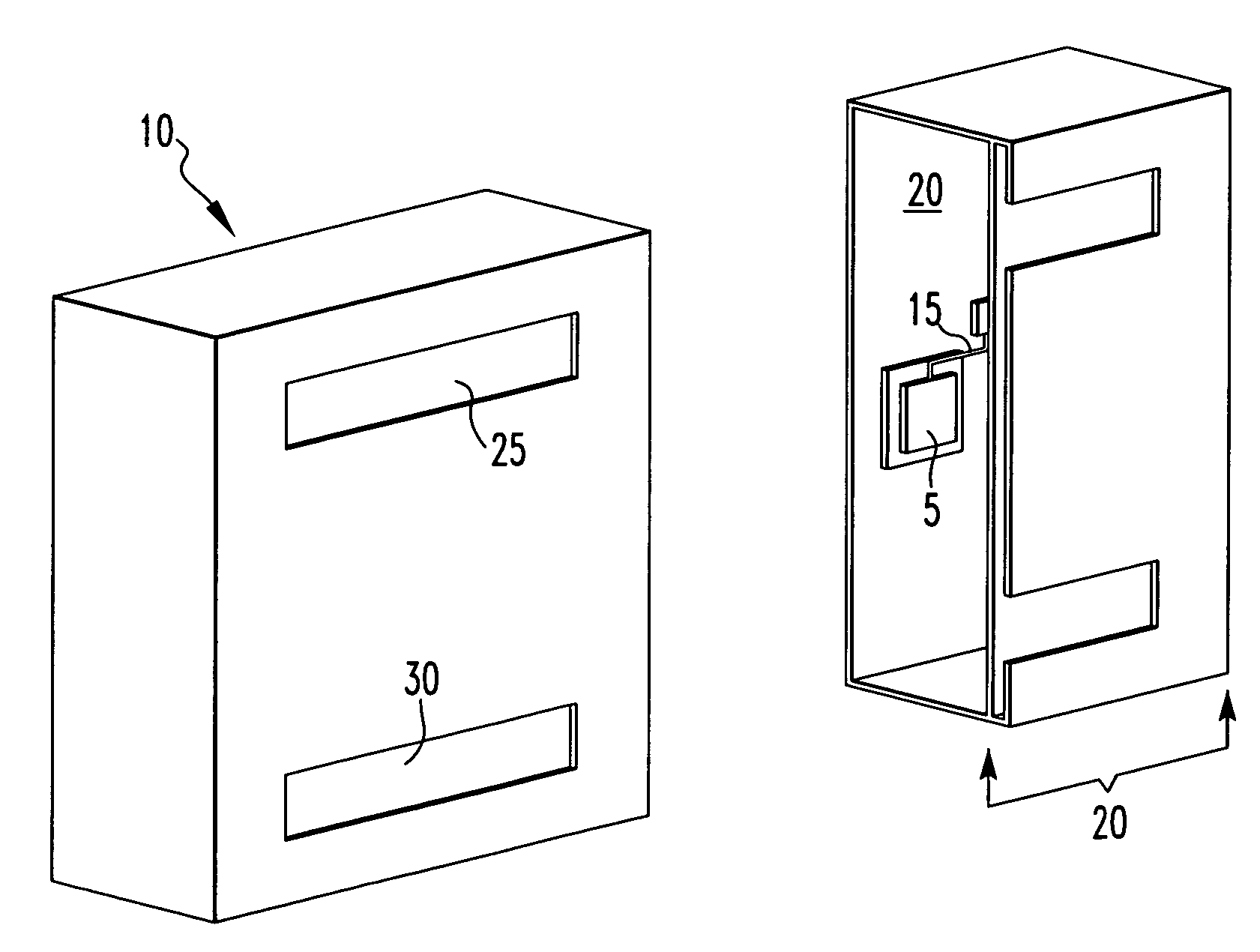
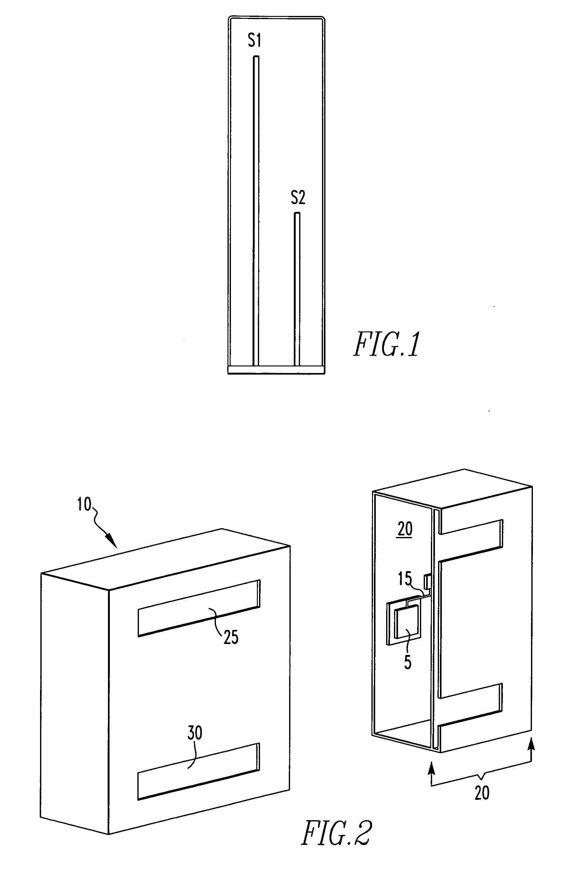
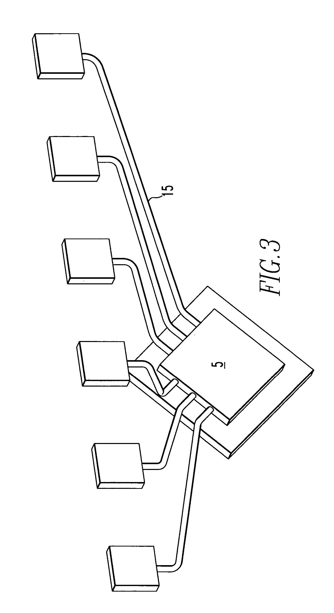
[0033] The present invention provides an electronics device enclosure having increased cooling to vent heated air from the interior of the electronics device enclosure without the use of mechanical means. More specifically, the inventive electronics device enclosure transfers heat from the heat producing electrical devices contained therein using at least one heat pipe in conductive communication to the housing of the electronics device enclosure.

[0034] The heat that is transferred from the heat producing electronics to the housing of the electronics device enclosure is then transferred to the exterior atmosphere by at least one sidewall having an air passage that displays a chimney effect. The chimney effect promotes venting of heated air while simultaneously drawing cooled air into the air passage. The present invention is now discussed in more detail referring to the drawings that accompany the present application. It is noted that in the accompanied drawings like and / or corresp...


PUM


Abstract

The present invention provides an electronics case including a housing having at least one sidewall having an air passage, wherein the air passage includes an intake and an exhaust; a heat producing structure contained by the housing; and at least one heat pipe in conductive communication with the heat producing structure and the sidewalls having the air passage. The air passage within the sidewall produces a chimney effect that vents heated air from the housing. The chimney effect may be produced by a sidewall having a fluted sidewall.

Description

FIELD OF THE INVENTION [0001] The present invention relates to controlling temperature in heat producing electronic devices. More specifically, the present invention provides an electronics enclosure that regulates the temperature of internal heat producing electronics by using a combination of heat pipes and air passages. BACKGROUND OF THE INVENTION [0002] Prior electronic enclosure designs or enclosures for heat producing computer devices suffer from the disadvantages of excessive noise, fluctuating internal temperature, and a lack of robustness in the cooling design of the enclosure. Furthermore, prior electronics enclosures do not provide warning signals that indicate to the user that the cooling of the electrical devices contained within the enclosure is inadequate. Furthermore, prior electronics enclosures do not automatically power down the electronic devices contained within the enclosure in response to adverse heating. [0003]FIG. 1 provides an example of a prior computer en...

Claims


Application Information

Patent Timeline
Patent Type & Authority Applications(United States)
IPC IPC(8): H05K7/20
CPCH05K7/20145
Inventor BHATTACHARYYA, RABINDRA KUMARFRIDY, JOSEPH MICHAELGHIARDI, DOMENIC A.JARVIS, GLENNSIEMON, JOHN THOMAS JR.VRANKA, PETER A.
Owner ARCONIC INC
Learn More