Methods for measuring growth rates of carbon nanotubes

a carbon nanotube and growth rate technology, applied in the direction of crystal growth process, chemically reactive gas, milk preparation, etc., can solve the problems of inability to easily distinguish between the growth mode and the root growth mode and the inability to readily measure the growth rate of the carbon nanotube at different temperatures

Active Publication Date: 2006-10-26
TSINGHUA UNIV +1
View PDF6 Cites 37 Cited by
  • Summary
  • Abstract
  • Description
  • Claims
  • Application Information

AI Technical Summary

Problems solved by technology

However, when adopting the conventional CVD method to synthesize a CNT array, the difficulty is that people do not readily know when the carbon nanotubes start their growth and when the growth has ceased.
Furthermore, peop...

Method used


Image

  • Methods for measuring growth rates of carbon nanotubes
  • Methods for measuring growth rates of carbon nanotubes
  • Methods for measuring growth rates of carbon nanotubes

Examples


Embodiment Construction

[0018] Reference will now be made to the drawings to describe embodiments of the present measuring method thereof, in detail.

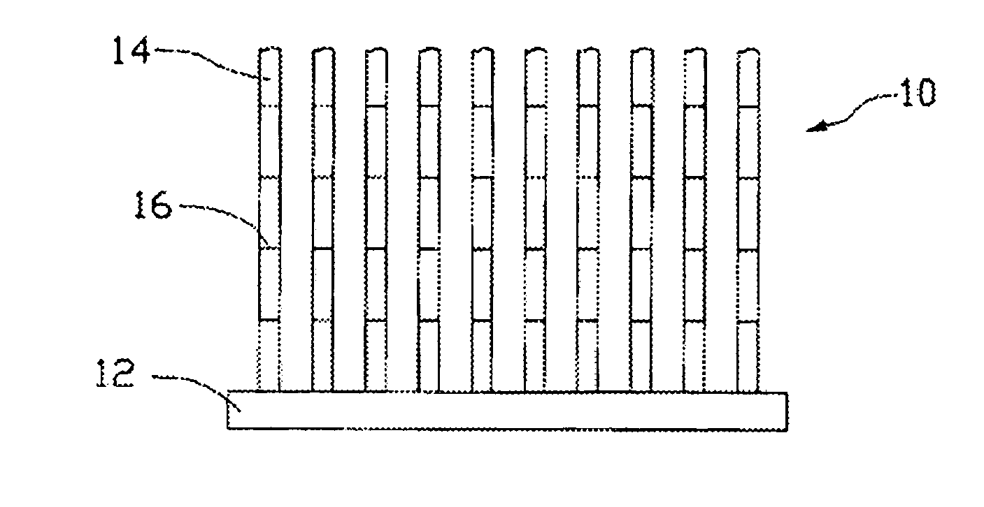
[0019]FIG. 1 is a schematic, side view of a carbon nanotube allay 10, in accordance with an exemplary embodiment of the present device. As shown in FIG. 1, the carbon nanotube array 10 includes a substrate 12 and a plurality of carbon nanotubes 14 formed on the substrate 12. The carbon nanotubes 14 are aligned in a substantially uniform direction. In the preferred embodiment, the carbon nanotubes 14 are substantially perpendicular to the substrate 12. Each carbon nanotube 12 has a plurality of line marks 16 separately formed thereon, and the carbon nanotube 12 is thereby divided into several, readily recognizable segments.

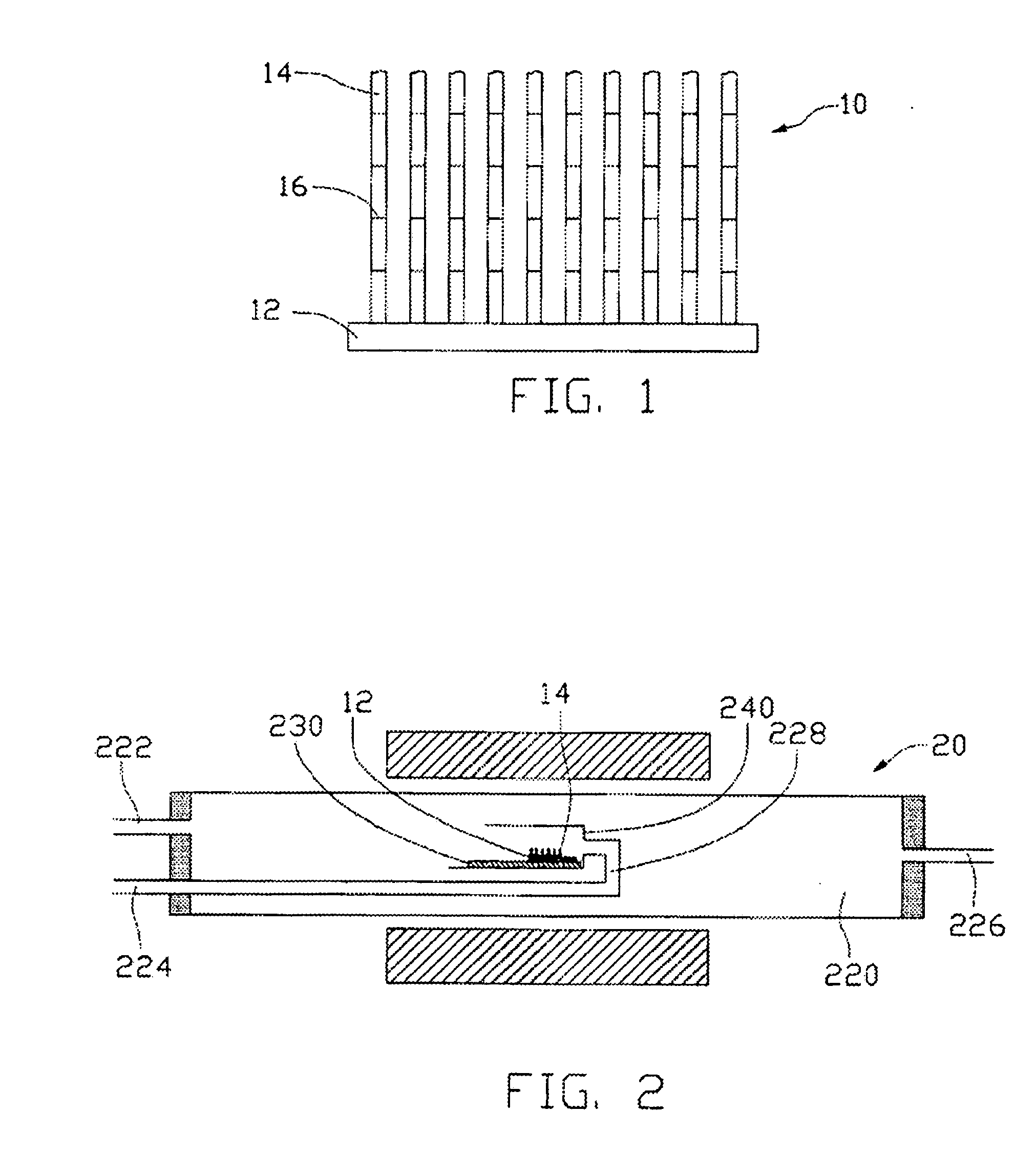
[0020]FIG. 2 is a schematic, side view of an exemplary device 20 adopted for manufacturing the carbon nanotube array of FIG. 1. As shown in FIG. 2, the device 20 is a reaction furnace and includes a reaction chamber 220, a gas introducing t...


PUM


Abstract

A method for measuring a growth rate of a carbon nanotube includes the following steps: (a) providing a substrate (12); (b) forming a catalyst layer on the substrate; (c) heating the substrate to a predetermined temperature; (d) intermittently introducing/providing and then interrupting a reaction gas proximate the substrate to grow a patterned carbon nanotube array, each carbon nanotube having at least one line mark formed thereon as a result of the patterned growth; and (e) calculating the growth rate which is equal to a length between a pair of line marks divided by a time interval between said two line marks.

Description

RELATED APPLICATIONS [0001] This application is related to commonly-assigned applications entitled, “CARBON NANOTUBE ARRAYS AND MANUFACTURING METHODS THEREOF”, filed ______ (Atty. Docket No. US7272) and “DEVICES FOR MANUFACTURING CARBON NANOTUBE ARRAYS”, filed ______ (Atty. Docket No. US7273), the content of both of which is hereby incorporated by reference. BACKGROUND [0002] 1. Field of the Invention [0003] The invention relates to methods for measuring a growth rate of a carbon nanotube. [0004] 2. Discussion of Related Art [0005] Carbon nanotubes (also herein refereed to as CNTs) are very small tube-shaped structures essentially having a composition of a graphite sheet in a tubular form. Carbon nanotubes have interesting and potentially useful electrical and mechanical properties and offer potential for various uses in electronic devices. Carbon nanotubes also feature extremely high electrical conductivity, very small diameters (much less than 100 nanometers), large aspect ratios ...

Claims


Application Information

Patent Timeline
IPC IPC(8): D01F9/12G01N31/10
CPCB82Y30/00B82Y40/00C01B31/0233C01B2202/08Y10T428/2931C30B29/602D01F9/127Y10T436/25875C30B25/14C01B32/162
Inventor JIANG, KAI-LILIU, KAIFAN, SHOU-SHAN
Owner TSINGHUA UNIV
Why Eureka
Try Eureka